Thursday, December 31, 2015

Prostate Cancer News - 2016-01-01


Prostate Cancer News - 2016-01-01


General Case Management


Choices you Make


Screening and Diagnosis


Biopsies, Genomics and Pathology


Tests


Imaging


Treatment

Active Surveillance


Surgery


Radiation


Hormone


Chemo


New Techniques


Side Effects


Advanced/Recurrence


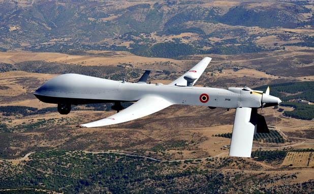
GA-ASI ends Predator-A RQ-1 UAV production with 2 to Italy

GA-ASI Delivers Final Two RQ-1 Predators to Italian Air Force
Italy receives Predator-A drones
The Italian Air Force has taken delivery of two Predator-A drones from General Atomics Aeronautical Systems Inc., the last two Predator-A systems being produced.
The remotely piloted aircraft will perform intelligence, surveillance and reconnaissance missions.
"With the delivery of these aircraft, GA-ASI completes over two decades of delivering Predator A capabilities to the United States and allied countries," said Frank W. Pace, president, Aircraft Systems, GA-ASI. "Amassing over 2.1 million cumulative flight hours and featuring the highest mission capable rate of any aircraft in the Air Force's inventory, Predators will continue to keep warfighters safe by equipping them with unparalleled situational awareness for many years to come."

Italian delivery marks end of General Atomics RQ-1 production
General Atomics says Italy now operates 15 of its unmanned aircraft, but would not reveal how many of each type at the customer’s request. It took delivery of its first RQ-1 in 2004, and has also procured six MQ-9s that were recently approved by the US government to carry weapons.
That suggests a total of nine Italian RQ-1s, which are used for intelligence gathering. The aircraft are particularly active over the Mediterranean Sea and in support of NATO operations.
The manufacturer says the last RQ-1 exited the production line in Poway, California, in September or October. Testing is completed at another site in the Palmdale region.

 Related/Background:

Wednesday, December 30, 2015

A key AHRQ Health Care Metric - HAC rates down - but not so much lately and with some surprising laggards

AHRQ Data Show HAC Rate Continues To Decline in 2013 |
Agency for Healthcare Research & Quality
Hospital-Acquired Condition (HAC) Reduction Program - Centers for Medicare & Medicaid Services
 
HHS: EHRs, Financial Incentives Have Helped Increase Patient Safety As HACS Decline 17 Percent | Healthcare Informatics Magazine | Health IT | Information Technology
The widespread adoption of electronic health records (EHRs) has helped reduce hospital-acquired conditions by 17 percent over the past four years, resulting in 87,000 fewer patient deaths in 2014 alone, according to data collected by the Agency for Healthcare Research and Quality (AHRQ).
AHRQ, which operates under the U.S. Department of Health and Human Services, notes that hospitals have made “substantial progress in improving safety” and credits several likely contributing causes, including improved use of EHRs and financial incentives.
The AHRQ report states that hospital patients experienced 2.1 million fewer hospital-acquired conditions (HACs) from 2010 to 2014, which also saved the healthcare system approximately $19.8 billion in costs.
However, AHRQ data also indicates that after three years of declines in the number of avoidable HACs, that rate hit a plateau in 2014. Data shows that there were 145 HACS per 1,000 discharges in 2010 and that figure dropped to 121 per 1,000 discharges in 2013 and has held steady in 2014.


Hospital-acquired condition rates down but not as significant as first appears - FierceHealthcare
Efforts to reduce hospital-acquired conditions (HACs) have led to 87,000 fewer patient deaths and nearly $20 billion in healthcare cost savings over a four-year period, according to a new report released by the Department of Health and Human Services. But the findings may not be as significant as they seem.
Although federal officials lauded the findings from the Agency for Healthcare Research and Quality (AHRQ), patient safety experts interviewed by Kaiser Health News said that while hospitals have made progress, the preliminary 2014 data isn't as impressive as it may initially appear. Indeed the findings were similar to an AHRQ report released last month that showed hospital complications were 17 percent lower in 2013 than 2010. But the 17 percent decline is the same statistic cited in the latest report that includes 2014 data.
"We are still trying to understand all the factors involved, but I think the improvements we saw from 2010 to 2013 were very likely the low-hanging fruit, the easy problems to solve," Richard Kronick, Ph.D., director of the federal AHRQ, told KHN.

Nearly 800 hospitals receive penalties for poor hospital-acquired condition scores - FierceHealthcare
The Centers for Medicare & Medicaid Services will levy a 1 percent reimbursement penalty against nearly 800 hospitals due to poor performance on hospital-acquired conditions (HACs), the agency announced.
Of the 3,308 U.S. hospitals subject to Medicare's HAC program this year, 758 received the penalty compared to 724 last year. Only about half of the penalized providers were subject to the same penalty last year. The facilities in question stand to lose about $364 million in reimbursements.
However, the agency said hospital scores improved for central-line infections, but dropped for catheter-related urinary tract infections. CMS has also added new quality information to its Hospital Compare site, adding data on group practices and accountable care organizations, the agency said, as well as its first set of performance measures for individual practitioners on patient safety, cardiovascular care and patient safety.

Fiscal Year (FY) 2016 Results for the CMS Hospital-Acquired Conditions (HAC) Reduction Program
Public Reporting
On December 10, 2015, CMS made the following HAC Reduction Program information publicly available for each eligible hospital:
  • PSI 90 Composite measure score
  • CLABSI, CAUTI, and SSI measure scores
  • Domain 1 and Domain 2 scores
  • Total HAC Score
The FY2016 HAC Reduction Program scores for hospitals can be found on the Hospital Compare Website by following this link:
https://www.medicare.gov/hospitalcompare/HAC-reduction-program.html
The list of hospitals subject to the payment adjustments are posted on the following CMS.gov website under this link:
https://www.cms.gov/Medicare/Medicare-Fee-for-Service-Payment/AcuteInpatientPPS/HAC-Reduction-Program.html

Six local hospitals fined by Medicare for preventable infections | SanDiegoUnionTribune.com
Too many patients still acquire infections and other potentially deadly yet avoidable complications, the government’s latest review of quality-control efforts at hospitals across the country shows.
The problem plagues hospitals large and small, including prestigious medical centers with a reputation for top-flight care. For example, Scripps Green Hospital in La Jolla and UC San Diego Medical Center’s campuses in Hillcrest and La Jolla have infection scores that put them in the worst 5 percent of hospitals nationwide.
Infections and other hospital-acquired conditions are hardly a new challenge. But they are getting greater attention as part of health reforms rolled out with the Affordable Care Act, also known as Obamacare.
They are also part of a push by regulators to compel hospitals to scrutinize every aspect of their operations, including the most mundane tasks, so patients recover faster, get discharged promptly and receive proper follow-up treatment so they do not have to be readmitted.
Health officials and an assortment of independent ratings groups look at whether doctors and nurses are following nationally recommended standards of treatment. They assess whether hospitals are doing enough training and enforcement to minimize medication errors, preventable falls, bedsores, surgical mix-ups and the like. They also evaluate the continuum of care between a hospital and its affiliated physician groups.

Hospital-Acquired Conditions - Centers for Medicare & Medicaid Services
These 14 categories of HACs listed below include the new HACs from the IPPS FY 2013 Final Rule which are Surgical Site Infection Following Cardiac Implantable Electronic Device (CIED) and Iatrogenic Pneumothorax with Venous Catheterization.  For FY 2014and FY 2015, there are no additional HACs added:
  1. Foreign Object Retained After Surgery
  2. Air Embolism
  3. Blood Incompatibility
  4. Stage III and IV Pressure Ulcers
  5. Falls and Trauma: Fractures, Dislocations, Intracranial Injuries, Crushing Injuries, Burn, and Other Injuries
  6. Manifestations of Poor Glycemic Control: Diabetic Ketoacidosis, Nonketotic Hyperosmolar Coma, Hypoglycemic Coma, Secondary Diabetes with Ketoacidosis, Secondary Diabetes with Hyperosmolarity, 
  7. Catheter-Associated Urinary Tract Infection (UTI)
  8. Vascular Catheter-Associated Infection
  9. Surgical Site Infection, Mediastinitis, Following Coronary Artery Bypass Graft (CABG):
  10. Surgical Site Infection Following Bariatric Surgery for Obesity: Laparoscopic Gastric Bypass, Gastroenterostomy, Laparoscopic Gastric Restrictive Surgery
  11. Surgical Site Infection Following Certain Orthopedic Procedures: Spine, Neck, Shoulder, Elbow
  12. Surgical Site Infection Following Cardiac Implantable Electronic Device (CIED)
  13. Deep Vein Thrombosis (DVT)/Pulmonary Embolism (PE) Following Certain Orthopedic Procedures: Total Knee Replacement, Hip Replacement
  14. Iatrogenic Pneumothorax with Venous Catheterization

Related/Background:
Hot off the NASA Presses - a 3-D Printed Rocket Engine

Engineers Zach Jones left, and Chris Protz examine the
first, full-scale 3-D printed copper engine part in
the additive manufacturing laboratory at Marshall.
Image Credit: NASA/MSFC/Emmett Given
The Marshall Star | NASA
Engineers prepare a 3-D printed breadboard engine made up of
75 percent of the parts needed to build a rocket engine for a
test at NASA’s Marshall Space Flight Center in Huntsville,
Alabama.Credits: NASA/MSFC/Emmett Given

Only a handful of copper rocket parts have been made with additive manufacturing, so NASA is breaking new technological ground by 3-D printing a rocket component that must withstand both extreme hot and cold temperatures and has complex cooling channels built on the outside of an inner wall that is as thin as a pencil mark. To increase U.S. industrial competitiveness, data will be made available to American manufacturers in NASA’s Materials and Processing Information System (MAPTIS) managed by Marshall.
“Our goal is to build rocket engine parts up to 10 times faster and reduce cost by more than 50 percent,” said Chris Protz, the Marshall propulsion engineer leading the project. “We are not trying to just make and test one part. We are developing a repeatable process that industry can adopt to manufacture engine parts with advanced designs. The ultimate goal is to make building rocket engines more affordable for everyone.”
The next step in this project is for Marshall engineers to ship the copper liner to NASA’s Langley Research Center, where an electron-beam, freedom fabrication facility will direct-deposit a nickel super-alloy structural jacket onto the outside of the copper liner. Later this summer, the engine component will be hot-fire tested at Marshall to determine how the engine performs under extreme temperatures and pressures simulating the conditions inside the engine as it burns propellant during a rocket flight.

NASA Team Moves Closer to Building a 3-D Printed Rocket Engine | NASA

A NASA team moved a step closer to building a completely 3-D printed, high-performance rocket engine by manufacturing complex engine parts and test firing them together with cryogenic liquid hydrogen and oxygen to produce 20,000 pounds of thrust.
Additive manufacturing, or 3-D printing, is a key technology for enhancing space vehicle designs and manufacturing and enabling more affordable exploration missions. The technology has the potential to influence spacecraft built for leaving Earth and spaceships and landers for visiting other destinations. Future plans include performing engine tests with liquid oxygen and methane--key propellants for Martian landers since methane and oxygen production might be possible on the Red Planet.
“We manufactured and then tested about 75 percent of the parts needed to build a 3-D printed rocket engine,” said Elizabeth Robertson, the project manager for the additively manufactured demonstrator engine at NASA’s Marshall Space Flight Center in Huntsville, Alabama. “By testing the turbopumps, injectors and valves together, we’ve shown that it would be possible to build a 3-D printed engine for multiple purposes such as landers, in-space propulsion or rocket engine upper stages.”


Models | 3D Resources (Beta)

Sunday, December 27, 2015

San Diego Winners in 2016 Spending bill

The mobile landing platform Lewis B. Puller (T-MLP-3/T-AFSB-1)
successfully completed launch and float-off at the General
Dynamics National Steel and Shipbuilding Co. (NASSCO)
shipyard on Nov. 6, 2014. US Navy Photo
USAF MQ-9 Reaper
Obama administration directs $250 million
toward fighting wildfires - LA Times
SDMAC Economic Impact Study
San Diego, CA - Today the San Diego Military Advisory Council (SDMAC) unveiled its 7th Annual SDMAC Military Economic Impact Study (SDMAC MEIS) at a press conference and luncheon at the Admiral Kidd Club located on Naval Base Point Loma. The annual study, commissioned by SDMAC and produced by the Fermanian Business and Economic Institute at Point Loma Nazarene University, solidifies the significant and tremendous impact the defense and military communities bring to the entire San Diego region - and the continuous threats of political gridlock and imposed budget caps. 

$25B in Defense Funds Expected in 2016: Report | NBC 7 San Diego

Highlights of the Department of the Navy FY 2016 Budget book.pdf

Spending bill bolsters San Diego | SanDiegoUnionTribune.com
  • Local Military Impact
    • School systems will get a little more cash for teaching military dependents. 
    • Service members are getting a 1.3 percent raise.
    • Military housing spending is going up.
  • Local Contractors
  • Local Government Projects
    • wildfire fighting and prevention spending.
    • Department of Transportation  Highway Trust Fund project financing for local projects eligible for those funds such as 
      • the Metropolitan Transit System’s rapid bus system, 
      • the San Diego Trolley (for improvements to platforms and new shelters), and 
      • new carpool lanes on I-805.

Wednesday, December 23, 2015

FAA tries to deal with proliferation of micro-UAV's


No Drone Zone

UAV Pilot Cited For Flying Aircraft Near Washington Monument | Aero-News Network
The Associated Press reports that in a news release, Park Police say that three people were flying a Wondertech Zenith UAV on the grounds of the monument last Thursday. Police cited 24-year-old William Stokes Jr. after ordering him to land the aircraft, which was confiscated.
The entire D.C. area is part of a "No Drone Zone" established by the FAA earlier this year. A "No Fly Zone" was imposed over the Nation's Capitol following the September 11, 2001 terrorist attacks. The "No Drone Zone" includes everything in a 15 mile radius of Ronald Reagan National Airport in Virginia.
Officials say that the most recent incident is the 10th illegal flight of a UAV in the national park in the Washington area this year.
 
So Your Neighbor Got a Drone for Christmas - Scientific American
Today thousands of people and businesses across the country fly drones, and that number is set to explode: The Federal Aviation Administration (FAA) anticipates that this holiday season people will purchase as many as one million drones. In an effort to control this flood of flying machines the FAA announced this week that it would require recreational drone users to register their aircraft. But a big question with major implications for the drone industry is far from being resolved: Who owns the airspace above private property? As Stuart Banner, a University of California, Los Angeles, law professor, puts it, “Drones are forcing people to think about this issue for the first time since airplanes were invented a century ago.”

FAA releases web-based system for small UAS registration - Military Embedded Systems
WASHINGTON. Owners of small unmanned aircraft (UAS) can use a new streamlined, web-based process to register their aircraft. U.S. Department Transportation’s Federal Aviation Administration (FAA) officials announced the new ruling during the holiday season.

“Make no mistake: unmanned aircraft enthusiast are , and with that title comes a great deal of responsibility,” says U.S. Transportation Secretary Anthony Foxx. “Registration gives us an opportunity to work with these users to operate their unmanned aircraft safely. I’m excited to welcome these new aviators into the culture of safety and responsibility that defines American .”
To register online, visit: www.faa.gov/uas/registration.

FAA Announces Rules for Aircraft Registration Process - FlyingGiants

  • Registration is required for: small unmanned aircraft (UAS) weighing more than 0.55 pounds (250 grams) and less than 55 pounds (approx. 25 kilograms).
  • Under this rule, any owner of a small UAS who has previously operated an unmanned aircraft exclusively as a model aircraft prior to December 21, 2015, must register no later than February 19, 2016.
  • Owners of any other UAS purchased for use as a model aircraft after December 21, 2015 must register before the first flight outdoors.
  • Owners may register through a web-based system at www.faa.gov/uas/registration.
  • Registrants will need to provide their name, home address and e-mail address. Upon completion of the registration process, the web application will generate a Certificate of Aircraft Registration/Proof of Ownership that will include a unique identification number for the UAS owner, which must be marked on the aircraft.
  • Owners using the model aircraft for hobby or recreation will only have to register once and may use the same identification number for all of their model UAS. The registration is valid for three years.
  • The normal registration fee is $5, but in an effort to encourage as many people as possible to register quickly, the FAA is waiving this fee for the first 30 days (from Dec. 21, 2015 to Jan 20, 2016).
FAA Issues Fact Sheet On State And Local UAS Laws | Aero-News Network
The FAA has issued a new fact sheet on state and local regulation of unmanned aircraft systems (UAS) which provides information for states and municipalities considering laws or regulations addressing UAS use. The document outlines FAA's safety reasons for federal oversight of aviation and airspace, and explains federal responsibility in this area.

FAA Announces Drone Registration Rules; Benefits Remain Unclear - Forbes
In a much-anticipated announcement this morning, the FAA unveiled its drone registration requirements in anticipation of what many experts predict will be a brisk drone-buying holiday season. As I’ve written about previously, the FAA – spurred by what it terms a dramatic increase in pilot reports of drones too close to manned aircraft – determined that registration was necessary to “increase accountability and education” of drone operators. (The data used by the FAA has been debunked by a number of people, including most recently the Academy of Model Aeronautics.)

Parsing The New UAV Registration Rule | Aero-News Network
The new UAV registration rule is "more activity than action," according to at least one attorney-turned-consultant who has been through the 211 pages of the rule.
An article posted to the blog JDA Journal by Consultant Sandy Murdock, who lists "Former FAA Chief Counsel and Acting FAA Deputy Administrator" as part of his vitae, asserts that the process of registration will not enhance safety in the national air space.
By now, we're all aware that any UAV that weighs more than 250 grams must be registered with the FAA. According to the blog, the Interim Final Rule (IFR) is 211 pages of single-spaced small text ... and about 180 of those are an introduction and explanation of the rule. Overall, less than 5 percent of the verbiage in the document is the actual rule.

Aviation Today :: Drone Registration for the Non-Hobbyist
The Dec. 16 Interim Final Rule most immediately applies to drone hobbyists operating under the “model aircraft” definition—aircraft used for non-commercial purposes and within visual line of sight. These applicants have been provided an online alternative to the paper-based aircraft registration system by way of a new 14 CFR Part 48. Every three years, they also will pay a $5 registration, which covers all of their drones.

FAA Finally Admits Names And Home Addresses In Drone Registry Will Be Publicly Available - Forbes
The FAA finally confirmed this afternoon that model aircraft registrants’ names and home addresses will be public. In an email message, the FAA stated: “Until the drone registry system is modified, the FAA will not release names and address. When the drone registry system is modified to permit public searches of registration numbers, names and addresses will be revealed through those searches.”

Monday, December 21, 2015

RAND - Funding Ship Maintenance a Big Problem

San Diego Ship Repair to Expand Capabilities
Navy Surface Fleet Faces Rough Waters Trying to Maintain Ships
The Navy in the past decade has found itself in a downward spiral of maintenance problems. It has subjected the fleet to high operational tempos that increased wear and tear and has cut back routine practices that help identify onboard repair needs, such as ship inspections and assessments.

The service is trying to revamp its maintenance policies to include more inspections, new technology and a shift in culture. Progress is occurring, but changes will take a while to stick, and the service will likely have to deal with budget cuts that make it more difficult to maintain its ships, Navy and industry officials said.

Water is drained from a dry dock at U.S. Naval Ship Repair
Facility and Japan Regional Maintenance Center (SRF JRMC)
Yokosuka preparing the Ticonderoga-class guided-missile
cruiser USS Shiloh (CG 67) for a scheduled maintenance
availability in July 2015. US Navy photo.
Navy Refining Surface Ship Master Plan to Balance Shipyard, Operational Needs - USNI News
SAN DIEGO – The Navy’s maintenance and operational communities have completed the first iterations of a surface ship master plan for maintenance and modernization work, in the hopes of balancing out peaks and valleys in shipyard workload without impacting operational needs.
The effort began after Fiscal Year 2013, when the Navy’s regional maintenance centers were performing as much as 40 percent more work than predicted, Rear Adm. Bill Galinis, deputy commander of surface warfare at Naval Sea Systems Command (NAVSEA) and commander of Navy Regional Maintenance Center, said at the American Society of Naval Engineers’ annual Fleet Maintenance and Modernization Symposium. In some cases, the estimates did not accurately predict how much repair work was needed, and in some cases the predictions only included mid-life work on older ships but forgot to include post-shakedown availabilities for brand new ships.


Assessment of Surface Ship Maintenance Requirements | RAND

Key Findings

Since the Late 1990s, Expenditures per Ship Are Growing at an Increasing Rate

  • This fact runs parallel to the legislative environment, which impact available resources. Annual shortfalls now amount to $8 billion between requested budget and legislatively authorized possible if legislation does not change.
  • Pressure on maintenance budgets is expected to grow as the effects of sequestration are felt, with no expected diminishment in the demand for naval forces.
  • Even absent sequestration, continued growth in per-ship maintenance cost is likely unsustainable, at least at the rate seen in the last 15 years. At the rate seen, maintenance would either become a larger component of the operations and management budget or come at the expense of new construction or modernization or require deferral.

A Study of the DDG-51 Class Shows the Mismatch Between Navy's Claims for Maintenance and What Is Spent

  • A comparison between the cumulative maintenance levels for the DDG-51 and the levels specified in the Navy's technical foundation papers showed that the Navy is not in general funding to the level as stated in the technical foundation papers.
  • This casts doubt on the validity of the technical foundation papers' requirements and the Navy's commitment to carrying out the maintenance stated in these published papers.
  • Given this, the Navy will need to consider alternatives to the technical foundation papers' process as it formulates requirements and source plans.

Deferred Maintenance of Ships Affected by Individual History of Ships

  • Ships of similar age and operating histories whose major difference is basing histories — with the attendant effects on maintenance — can show dramatic differences between the overall costs to maintain.
  • Maintenance deferrals exact an extremely high premium that drives ship cost up in ways inconsistent with the need to contain costs.
  • Any maintenance construct needs to understand and budget for the high cost of deferral or devise mitigations for cases where deferral is inevitable.

Recommendations

This report recommends actions the Navy can take to address surface ship maintenance and operations requirements in the context of fiscal constraints.

  • A maintenance strategy that prioritizes selected restricted availabilities (SRAs), which are relatively lengthy and well funded, but the time and money available for maintenance in SRAs is limited. Maintenance priorities within SRAs are assigned based on safety concerns, the predictability of failures, the consequences of failures, and the future cost of deferring maintenance.
  • If the maintenance required is relatively straightforward, and can be conducted with available personnel or can be broken down into manageable segments, then a continuous maintenance availability can provide an efficient and cost-effective alternative to an SRA.

How a medical device maker kept U.S. hospitals in the dark about deadly infections - Los Angeles Times

A 2012 inspection by Olympus and Dutch hospital
officials revealed a brown film inside a duodenoscope.
(Arjo Loeve / Delft University of Technology)
How a medical device maker kept U.S. hospitals in the dark about deadly infections - Los Angeles Times
Over the next three years, 21 people died and at least two dozen more became ill from infections related to scopes in Pittsburgh, Seattle and Los Angeles. An unknown number of other patients have been infected. The Food and Drug Administration has identified 10 outbreaks, seven of which involve Olympus scopes.
Even as patients died and others were put at risk, Olympus continued to sell the device and failed to warn U.S. hospitals that the scopes were tied to dangerous infections, according to interviews with dozens of hospital officials, doctors, regulators and former Olympus employees.
In February 2015, immediately after the UCLA outbreak was reported, Olympus sent an alert to customers. It disclosed, for the first time, that it was aware of 95 complaints tying its scope to patient infections.

Related/Background:

Sunday, December 20, 2015

Key ITU WRC-15 Spectrum Decisions

World Radiocommunication Conference 2015
World Radiocommunication Conference 2015 Decides Satellite Spectrum is Central to Future Vision for Global Connectivity | Business Wire
Among the key decisions made during WRC [Newsroom: WRC-15 and RA-15] are the following:
  • L-band
    • WRC-15 avoided identification of the L-band spectrum, which is used by mobile satellite service operators around the world, for IMT— International Mobile Telecommunication system. 
    • The Conference identified the band 1427-1518 MHz for IMT, requesting the ITU-R to determine the technical measures to ensure compatibility with the mobile-satellite service operations in the adjacent band (1518-1559 MHz).
  • C-band
    • WRC-15 reconfirmed the need to protect critical fixed-satellite service (FSS) services throughout the world in this unique band. 
    • The lower 200 MHz of the C-band downlink frequencies (3400-3600 MHz) were identified for IMT in ITU Regions 1 and 2; In Region 3 a handful of countries will sign a footnote allowing potential IMT use of these 200 MHz, while the vast majority of the region will continue satellite use of this band with no change. 
    • A position of “No Change” was adopted in the band 3600-4200 MHz, and only in Region 2 was a footnote agreed which identified IMT for a few countries in the 3600-3700 MHz band. 
    • A “No Change” decision means that administrations have recognised the vital and widespread use of those frequency bands by satellite services. 
    • Anywhere that IMT is deployed, it will be subject to adherence to strict protection requirements with neighbouring countries. 
    • In addition, the Conference declined to consider a proposal for IMT systems in the C-band uplink frequencies (5925-6425 MHz).
  • Ku-band
    • In order to address a spectrum imbalance in Ku-band spectrum, WRC-15 identified additional spectrum for FSS systems between 10-17 GHz. 
    • A downlink allocation in the 13.4-13.65 GHz band in Region 1 (EMEA) was approved by the Conference. 
    • In addition, an allocation in the 14.5-14.8 GHz was approved in several countries around the world.
  • Future bands for 5G
    • The Conference decided that no globally harmonised bands for the fixed satellite service, mobile-satellite service and broadcast-satellite service in C, Ku or Ka band would be included in the scope of a new WRC-19 agenda item, which aims to identify new frequency bands for future IMT/ 5G use. 
    • Throughout the deliberations, multiple administrations in every world region expressed strong opposition to studying the Ka band for IMT/5G, again confirming the Conference’s confidence in satellite being a key player in the future digital eco-system.
  • ESIMs
    • The Conference adopted new regulations to facilitate the operation of “Earth Stations in Motion” (ESIMs) in part of the Ka-band satellite spectrum (19.7-20.2 GHz and 29.5-30 GHz). 
    • ESIMs operating in this band provide satellite broadband connectivity to mobile terminals, such as on ships and aircraft. 
    • The new regulations adopted by WRC-15 will facilitate the global roaming of such terminals, while protecting other services and applications from interference.
  • Other: WRC-15 adopted several agenda items for future conferences that will spur growth in the satellite industry. 
    • Studies were approved for WRC-19 for additional FSS spectrum in 51.4-52.4 GHz. 
    • In addition, the conference adopted a future agenda item for WRC-23 for additional satellite spectrum in the 37.5-39.5 GHz. 
    • Also, in a hotly contested debate, the Conference adopted a Resolution which sets the path towards allowing the use of FSS links for Unmanned Aerial Systems (UAS).


Spectrum decisions at WRC-15, a step towards the Networked Society
Following the conclusion of the International Telecommunication Union (ITU) World Radiocommunication Conference 2015 (WRC-15), Ericsson (NASDAQ: ERIC) acknowledges the decision to make additional spectrum available for mobile broadband as a step towards achieving the full potential of a Networked Society.
Held in Geneva, Switzerland, between November 2 and November 27, 2015, the WRC-15, representing regulators from around the world, reached agreement and identified new spectrum for mobile communications for international mobile telecommunications (IMT), which is the collective term for 3G, 4G and 5G.
  • A decision was reached to make the L-Band (1427 – 1518MHz) and part of the C-Band (3.4 – 3.6GHz) are available for mobile broadband on a global basis.
  • The 700MHz band (694 – 790MHz) is now also globally harmonized following the initial decisions made at WRC-12 and the follow-up action at WRC-15 for its use in Europe, Middle East and Africa.
  • Additional spectrum is identified in some countries in the frequency bands 470 – 694/698MHz, 3.3-3.4GHz, 3.6-3.7GHz and 4.8 – 4.99GHz.
  • Spectrum at higher frequencies in the range from 24.25GHz up to 86GHz will be subject to study work for 5G (IMT-2020) usage in ITU, providing one of the cornerstones for future 5G services.

Groups Welcome WRC-15 Spectrum Decisions | EE Times
As predicted in a previous post there was lively interest in and a surprisingly high level of agreement in deliberations around the fate of the 700MHz and sub-700 MHz bands.
“The outcome was as satisfactory as we could have expected as regards more spectrum for mobile broadband, while keeping broadcasters satisfied. There was a lot of pressure on them not to yield,” Mike Goddard, International Spectrum Policy Adviser for consultancy Real Wireless told EE Times.
Goddard was for long CEO of the UK’s Radio Communications Agency and also led the UK delegation to the WRC between 1987 and 2007. “As usual, a lot of decisions were left to the last moment, with delegations reluctant to give way on some key decisions, and it got a bit crazy in the end, but overall, I would say it was a successful WRC, with very important conclusions and a clear and ambitious view of the topics we need to address at WRC 2019,” said Goddard.
In addition to confirming the use of the 700 MHz band (technically 694 to 790 MHz) for mobile broadband services in ITU Region 1, which includes Europe, Africa, the Middle east and Central Asia, delegates also agreed to harmonize 200 MHz of the C-band (3.4 to 3.6 GHz) to improve capacity in urban areas and used in small cells, and the L-band (1427-1518 MHz) to improve overall coverage and better capacity.
However, despite intense lobbying from mobile broadband groups, delegates from some 150 countries decided against opening up more sub-700 MHz spectrum to the sector, ensuring that UHF spectrum (470 MHz to 690 MHz) will remain exclusively allocated to terrestrial TV services in Region1, for at least a decade. Delegates decided to review the use of these bands not at the next WRC, but the one planned for 2023.

Related/Background:

Thursday, December 17, 2015

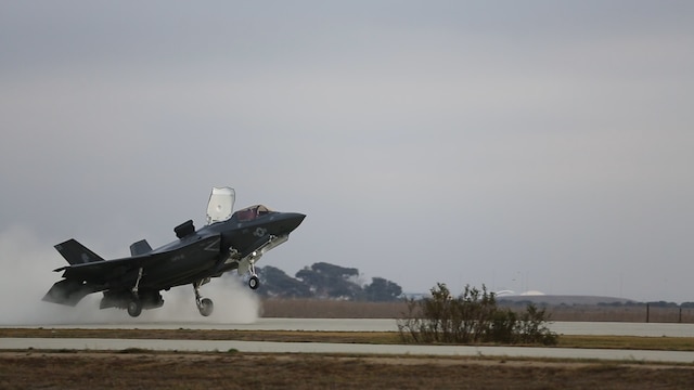
Marine Corps F-35s not set to do Cactus Air Force Ops

Exercise Raises Questions About Marine Corps F-35 Plans
PARIS --- Five months after it declared Initial Operational Capability of the F-35B fighter, and 14 years after award of the aircraft’s development contract, the Marine Corps is looking at how it will integrate the aircraft into its expeditionary units.

One of the first integration exercises, known as Steel Knight 2016, is taking place in Southern California, and has highlighted potential mismatches between Marine Corps plans for the F-35B and reality.

The Marine Corps is spending tens of billions of dollars to buy the F-35B Short Take-Off and Vertical Landing (STOVL) variant, which it says it needs to quickly deploy to beachheads to provide close air support to landing forces. Yet, the mechanics of getting it ashore are complex, and may make shore basing impossible.

“Quickly” is a relative concept, and the timelines necessary to prepare forward bases may be at odds with Marine amphibious warfare plans.


For example, one of four press releases issued to date about Exercise Steel Knight reveals for the first time that the Corps expects that building a 40,800 sq. ft. landing pad for the F-35B will take two months, although this time it was done in 17 days.

MWSS-374 undertook the project of creating the landing zone in just under two and a half weeks, a task that was projected to take two months. The task depended on the heavy equipment required, to remove four inches of concrete before any other work could be done on the site.

“One of the biggest challenges we face in the construction of a landing zone is getting the sand to compact as needed,” said Staff Sgt. John A. Vasquez, an engineer equipment operator with MWSS-374. “It took my Marines 17 long days to ensure the pad was put together.”

Related/Background:


Cactus Air Force - Wikipedia, the free encyclopedia 

CryoSat SIRAL Surveys Earth’s shifting ice and sea

Instruments / CryoSat / Observing the Earth / Our Activities / ESA
CryoSat’s primary instrument is the Synthetic Aperture Interferometric Radar Altimeter (SIRAL). It was designed to meet the measurement requirements for ice-sheet elevation and sea-ice freeboard, which is the height of ice protruding from the water.  The CryoSat altimeter sends a burst of pulses at an interval of only about 50 microseconds. The returning echoes are correlated and, by treating the whole burst together, the data processor can separate the echo into strips arranged across the track by exploiting the slight frequency shifts, caused by the Doppler effect, in the forward- and aft-looking parts of the beam. Each strip is about 250 m wide and the interval between bursts is arranged so that the satellite moves forward by 250 m each time. The strips laid down by successive bursts can therefore be superimposed on each other and averaged to reduce noise. This mode of operation is known as the Synthetic Aperture Radar – or SAR – mode.


Space in Videos - 2015 - 12 - Earth’s shifting ice


Carrying an advanced radar altimeter, CryoSat orbits Earth at just over 700 km, reaching latitudes of 88° north and south to maximise its coverage of the poles.
The radar altimeter is not only able to detect tiny variations in the height of the ice but also measure sea level with unprecedented accuracy.
As the animation shows, the mission’s measurements of sea level incidentally also map the topography of the ocean floor, revealing thousands of previously unchartered ‘seamounts’, ridges and deep ocean structures.
This animation visualises the changes the satellite has seen on Earth since its launch in 2010.

Related/Background:

  • Scagliola, M.; Fornari, M.; Tagliani, N., "Pitch Estimation for CryoSat by Analysis of Stacks of Single-Look Echoes," in Geoscience and Remote Sensing Letters, IEEE , vol.12, no.7, pp.1561-1565, July 2015
    doi: 10.1109/LGRS.2015.2413135
    Abstract: This letter describes a novel approach to retrieve the pitch of the CryoSat satellite by the analysis of Synthetic Interferometric Radar ALtimeter (SIRAL) acquisitions in synthetic aperture radar (SAR) or SAR-interferometric mode over ocean. The power distribution of the single-look echoes, which are gathered for each sample location on the Earth surface, has been verified to be modulated by the along-track antenna pattern. Thus, the actual antenna pointing direction can be retrieved by fitting the model of the along-track antenna pattern on the power distribution of a stack, which is a collection of single-look echoes referred to the same ground location but acquired from different look angles. With the pitch measurement being independent of the attitude information returned by the onboard star trackers, by comparison of the pitch measured from data and of the pitch from the star tracker, the existence of a bias on the pitch can be verified. Exploiting the proposed approach, the pitch returned by star trackers on CryoSat has been found to be biased by about 0.0533°, confirming similar results obtained by other methods proposed in the literature. It is worth noticing that the method for pitch estimation here described is not limited to CryoSat but can be applied to any SAR altimeter without loss of generality.
    keywords: {antennas;cryostats;echo;oceanographic techniques;radar altimetry;synthetic aperture radar;CryoSat satellite;SAR-interferometric mode;along-track antenna pattern;antenna pointing direction;ocean;onboard star trackers;pitch estimation;pitch measurement;power distribution;single-look echoes;stacks analysis;synthetic aperture radar;synthetic interferometric radar altimeter acquisitions;Antennas;Radar tracking;Satellites;Sea measurements;Sea surface;Synthetic aperture radar;Altimetry;CryoSat;calibration;mispointing;synthetic aperture radar (SAR)},
    URL: http://ieeexplore.ieee.org/stamp/stamp.jsp?tp=&arnumber=7080848&isnumber=7067019

    Patel, A.; Paden, J.; Leuschen, C.; Kwok, R.; Gomez-Garcia, D.; Panzer, B.; Davidson, M.W.J.; Gogineni, S., "Fine-Resolution Radar Altimeter Measurements on Land and Sea Ice," in Geoscience and Remote Sensing, IEEE Transactions on , vol.53, no.5, pp.2547-2564, May 2015
    doi: 10.1109/TGRS.2014.2361641
    Abstract: Satellite radar altimeter (RA) measurements are important for continued monitoring of rapidly changing polar regions. In 2010, the European Space Agency launched CryoSat-2 carrying SIRAL, a Ku-band RA with objectives of determining the thickness and extent of sea ice and the topography of the ice sheets. One difficulty with Ku-band radar surveys over snow and ice is unknown penetration of RA signal into snow cover. Improving our understanding of the interactions of RA signals with snow and ice is needed to produce accurate elevation products. To this end, we developed a low-power, ultrawideband (12-18 GHz) RA for airborne surveys to provide fine resolution measurements capable of detecting both scattering from the surface and layers within sea ice and ice sheets. These measurements provide a means of identifying the dominant scattering location of lower resolution RA measurements comparable to satellite-based instruments. We generated two products: a full-bandwidth waveform (FBW) to identify scattering targets at fine resolution and a reduced-bandwidth waveform (RBW) to represent conventional RA measurements. Retrackers are used to generate height estimates over various surface conditions for comparisons. Over ice sheets, the leading-edge tracker provided consistent ice-surface elevation measurements between the FBW and RBW results; however, there were significant differences between the results from the centroid tracker. Over sea ice, the location of the dominant return between the results from snow-covered sea ice is highly variable. This paper provides an overview of RA surveys in polar regions, a description of the CReSIS system, and a discussion of the results.
    keywords: {glaciology;radar altimetry;remote sensing by radar;sea ice;snow;topography (Earth);AD 2010;CReSIS system;ESA CryoSat-2;European Space Agency;SIRAL instrument;airborne surveys;fine resolution radar altimeter measurement;full bandwidth waveform;ice sheet topography;polar region monitoring;reduced bandwidth waveform;sea ice;snow;Radar;Satellites;Sea ice;Sea measurements;Sea surface;Snow;Airborne radar;frequency-modulated continuous wave (FMCW);radar altimetry review;sea ice;snow;ultrawideband radar},
    URL: http://ieeexplore.ieee.org/stamp/stamp.jsp?tp=&arnumber=6936928&isnumber=7001732

    Dusseaux, R.; Afifi, S.; Dechambre, M.; Legresy, B., "Simulations of the altimetric signal intensity from 3D-layered air/snow/sea-ice rough interfaces," in General Assembly and Scientific Symposium (URSI GASS), 2014 XXXIth URSI , vol., no., pp.1-2, 16-23 Aug. 2014
    doi: 10.1109/URSIGASS.2014.6929595
    Abstract: Remote sensing of the sea-ice thickness is one of the main objectives of the Ku-band radar altimeter SIRAL-CRYOSAT II mission. On the one hand, sea-ice thickness is derived from the measurement of the height of the freeboard of the floes, and based on isostasy, assuming that the density of the water, the ice, as well as the snow, are known. On the other hand even if the snow load is known, the penetration of the electromagnetic waves into the snow strongly depends on the electrical and geophysical characteristics of the snow layer (density, temperature, permittivity, roughness). The remote sensing of the snow layer thickness (SLT) remains a real challenge and will be useful to correct the snow load for converting freeboard measurements from satellite altimetry into sea-ice thickness. If the dual frequency radar altimetry data show a good potential for remote sensing of snow and more generally of penetrating media [1], providing the SLT from Ku band data alone is highly motivated by the orbit of CRYOSAT designed to cover the entire Arctic. In this framework, a theoretical study, based on a 3D modelling of the scattering of electromagnetic waves by a stratified medium at normal incidence has been carried out in order to investigate and quantify the capacity of snow and ice penetration of Ku-band waves. The stratified medium is modelled as a snow layer considered as a stack of 2 sub-layers and the boundary layer at the bottom represented by a semi-infinite layer of ice-sea as shown on the figure 1. The roughness of each interface is taken into account and the small slope approximation (SSA) is used to determine the coherent and incoherent components of the scattered intensity [2-4]. It is demonstrated that the coherent intensity is the the specular direction but it depends on the rms-roughness heights and does not depends on the shape of the correlation function. The incoherent intensity depends even on the rms-roughness heights, but also on the shape of the correlati- n function. Several simulations have been conducted by varying the permittivity, thickness and roughness of each interface [5-6]. The 3 interfaces are random processes with Gaussian autocorrelation functions with zero mean values. The main conclusion is that the backscattered signal from the stratified medium is strongly related to the dielectric characteristics. It can vary significantly even if the variations of the stratified medium are small. This is an important result to be kept in mind when attempting the signal inversion. In addition, another similar study based on a 2D modelling of the scattering of electromagnetic waves by the same stratified medium at normal incidence and simulations in the same conditions have been previously conducted [7]. The roughness of each interface was also taken into account and the first-order small perturbation method (SPM) was used to determine the coherent and incoherent components of the scattered intensity. Results from those two studies are also compared at the end.
    keywords: {air;electromagnetic wave scattering;geophysical signal processing;height measurement;oceanographic techniques;remote sensing;sea ice;snow;3D layered air-snow-sea ice rough interfaces;Gaussian autocorrelation function;SIRAL-CRYOSAT II mission;altimetric signal intensity;dielectric characteristics;electromagnetic waves scattering;freeboard measurements;remote sensing;sea ice thickness;signal inversion;small perturbation method;small slope approximation;water density;Electromagnetic scattering;Radar remote sensing;Remote sensing;Sea ice;Snow;Spaceborne radar},
    URL: http://ieeexplore.ieee.org/stamp/stamp.jsp?tp=&arnumber=6929595&isnumber=6928981

    Fornari, M.; Scagliola, M.; Tagliani, N.; Parrinello, T.; Garcia Mondejar, A., "CryoSat: Siral calibration and performance," in Geoscience and Remote Sensing Symposium (IGARSS), 2014 IEEE International , vol., no., pp.702-705, 13-18 July 2014
    doi: 10.1109/IGARSS.2014.6946520
    Abstract: CryoSat's Synthetic Interferometric Radar Altimeter (SIRAL) [1] is a Ku-band pulsewidth limited radar altimeter that transmits pulses at a high pulse repetition frequency thus making the received echoes phase coherent and suitable for De-lay/Doppler processing [2]. Moreover SIRAL takes advantage of two antennas mounted across-track for interferometric capability, in order to determine the across-track direction from which the echo is received [3]. The calibration strategy for SIRAL includes both internal calibrations and external calibration [1]. Due to the fact that SIRAL is an interferometric phase coherent pulse-width limited radar altimeter, a proper calibration approach has been developed. In this paper we will describe as first the internal calibration strategy and then the different calibration corrections that are applied to science data. The internal calibration results over more than three years of mission will be presented, analysing their temporal evolution in order to highlight the stability of the instrument over its life. Finally, the external calibration measurements for SIRAL will be presented.
    keywords: {Doppler effect;calibration;geophysical techniques;radar altimetry;radar cross-sections;radar interferometry;CryoSat synthetic interferometric radar altimeter;Doppler processing;Ku-band pulsewidth limited radar altimeter;SIRAL calibration;SIRAL calibration strategy;SIRAL performance;across-track direction;delay processing;external calibration;high pulse repetition frequency;interferometric capability;interferometric phase coherent pulse-width limited radar altimeter;internal calibrations;received echoes;temporal evolution;Calibration;Delays;Gain;Gain control;Instruments;Radar;Transponders;Altimetry;CryoSat;calibration},
    URL: http://ieeexplore.ieee.org/stamp/stamp.jsp?tp=&arnumber=6946520&isnumber=6946328

    Villladsen, H.; Andersen, O.B.; Stenseng, L., "Annual cycle in lakes and rivers from CryoSat-2 altimetry — The Brahmaputra river," in Geoscience and Remote Sensing Symposium (IGARSS), 2014 IEEE International , vol., no., pp.894-897, 13-18 July 2014
    doi: 10.1109/IGARSS.2014.6946569
    Abstract: A key concern of the CryoSat-2 orbit has been its long repeat period of 369 days, which is usually undesirable for river and lake monitoring. However, the results of this study show that CryoSat-2 data can indeed be used for such monitoring by utilizing the high spatial coverage and the sub-cycle period of 30 days. The performance of CryoSat-2/SIRAL altimetry for river level monitoring is investigated by studying river levels retrieved from Ganges and Brahmaputra. An evaluation of CryoSat-2 river levels from LRM, SAR and SARIn data is performed by comparing with Envisat data from the period in which the two missions overlapped (2010-2012). Time series constructed using simple linear interpolation are fitted with a model to compare the captured annual signals and amplitudes. The annual cycles seen in CryoSat-2 and Envisat altimetry data agree very well and provide confidence in using CryoSat-2 data to continue river level archives from satellite radar altimetry.
    keywords: {lakes;remote sensing by radar;rivers;AD 2010 to 2012;Brahmaputra river;CryoSAT-2 altimetry;CryoSat-2 altimetry data;CryoSat-2 data;CryoSat-2 orbit;CryoSat-2 river levels;CryoSat-2-SIRAL altimetry;Envisat altimetry data;Envisat data;LRM data;SARIn data;lake annual cycle;lake monitoring;river annual cycle;river level archives;river level monitoring;river monitoring;satellite radar altimetry;Altimetry;Lakes;Monitoring;Radar tracking;Rivers;Satellites;Time series analysis;Brahmaputra;CryoSat;Envisat;hydrology;inland waters;satellite altimetry},
    URL: http://ieeexplore.ieee.org/stamp/stamp.jsp?tp=&arnumber=6946569&isnumber=6946328

    Galin, N.; Wingham, D.J.; Cullen, R.; Francis, R.; Lawrence, I., "Measuring the Pitch of CryoSat-2 Using the SAR Mode of the SIRAL Altimeter," in Geoscience and Remote Sensing Letters, IEEE , vol.11, no.8, pp.1399-1403, Aug. 2014
    doi: 10.1109/LGRS.2013.2293960
    Abstract: This letter describes the retrieval of the pitch of the CryoSat-2 satellite from the full bit rate (FBR) SAR mode data that are collected over the ocean by the SAR/Interferometric Radar Altimeter (SIRAL). Starting with the FBR SAR mode data, we form beams at the forward and backward look angles with respect to the nadir direction. If the satellite is flying pitched, the asymmetrical weighting of the echo power in the forward-looking and backward-looking beams that resulted from the along-track antenna gain pattern is used to measure the pitch of the satellite. The method depends on accurate knowledge of the orbit and the altimeter echoes only. In consequence, we are able to compare the results with the contemporaneous pitch value that is measured by the onboard star trackers, and particularly, we are able to determine a bias in the star tracker pitch measurements. We find that the star trackers' pitch measurements are biased, with a constant offset of 0.055 ° ± 0.0073 °. Because the star tracker attitude is used to inform the onboard control system, this bias implies that CryoSat-2 is flying nose up, with an average pitch of about 0.055 °.
    keywords: {radar altimetry;radar antennas;remote sensing by radar;synthetic aperture radar;CryoSat-2 pitch;CryoSat-2 satellite;FBR SAR mode data;SAR-Interferometric Radar Altimeter;SIRAL altimeter;along-track antenna gain pattern;altimeter echoes;backward look angle;echo power asymmetrical weighting;forward look angle;full bit rate;onboard control system;star tracker pitch measurements;synthetic aperture radar;Extraterrestrial measurements;Oceans;Power distribution;Satellites;Sea measurements;Synthetic aperture radar;Vectors;Altimetry;CryoSat-2;calibration;mispointing;pitch;synthetic aperture radar (SAR)},
    URL: http://ieeexplore.ieee.org/stamp/stamp.jsp?tp=&arnumber=6709791&isnumber=6763141

    Galin, N.; Wingham, D.J.; Cullen, R.; Fornari, M.; Smith, W.H.F.; Abdalla, S., "Calibration of the CryoSat-2 Interferometer and Measurement of Across-Track Ocean Slope," in Geoscience and Remote Sensing, IEEE Transactions on , vol.51, no.1, pp.57-72, Jan. 2013
    doi: 10.1109/TGRS.2012.2200298
    Abstract: This paper describes the calibration of the CryoSat-2 interferometer, whose principal purpose is to accurately measure the height of the Antarctic and Greenland ice sheets. A sequence of CryoSat-2 data acquisitions over the tropical and midlatitude oceans were obtained between June and September 2010, from the SIRAL “A” and redundant SIRAL “B” radars operating in their “SARIN” mode, during a sequence of satellite rolls between -0.6° and 0.4°. Using the arrival angle of the echo relative to the interferometer baseline, the attitude of the satellite determined by the star trackers, and estimates of the ocean surface across-track slope from the EGM08 geoid, we determined the errors in the interferometer estimate of surface slope as functions of the roll angle and ocean surface waveheight. These were found to be in close agreement with the theoretical description. The scale factor of the interferometric measurement of angle was determined to be 0.973 ± 0.002. We estimate the accuracy of the across-track slope measurement of the interferometer by applying this scale factor to the measured phase. In applying this scale factor to the measurements, the across-track slope of the marine geoid was obtained with an accuracy of 26 μrad at 10 km and 10 μrad at 1000 km. We conclude that the instrument performance considerably exceeds that needed for the accurate determination of height over the sloping surfaces of the continental ice sheets. The results also demonstrate that CryoSat-2 provides the first observations of the instantaneous vector gradient of the ocean surface, and that the normal-incidence interferometric configuration has a greater potential for the measurement of the ocean across-track slope than has been previously recognized.
    keywords: {calibration;geophysical equipment;glaciology;AD 2010 06 to 09;Antarctic ice sheet;CryoSat-2 Interferometer;EGM08 geoid;Greenland ice sheet;SARIN mode;SIRAL A radar;SIRAL B radar;across track ocean slope;calibration;data acquisitions;ocean surface waveheight;roll angle;scale factor;Radar tracking;Satellites;Sea measurements;Sea surface;Surface waves;Calibration;CryoSat-2;interferometry;radar altimetry},
    URL: http://ieeexplore.ieee.org/stamp/stamp.jsp?tp=&arnumber=6227346&isnumber=6387651

    Meloni, M.; Vingione, G.; Ferrazzoli, P.; Parrinello, T., "Recent developments in radar altimetry over land and applications to future altimetric missions," in Geoscience and Remote Sensing Symposium (IGARSS), 2012 IEEE International , vol., no., pp.4594-4597, 22-27 July 2012
    doi: 10.1109/IGARSS.2012.6350445
    Abstract: Satellite radar altimetry, which was initially designed for accurate measurements of sea surface height, has been demonstrated to be suitable for land surfaces as well. In this paper, a simplified expression of the flat surface impulse response (PFS), which enters in the computation of the radar Impulse Response (IR), has been found which is valid for a nadir pointing system as well as for small mis-pointing angles. On the basis of this model, simulations have been performed taking into account the system characteristics of the new sensor SIRAL (Cryosat-2), considered operating in LRM (Low Resolution Mode) varying some key parameters such as backscattering coefficient, off-nadir angle, surface RMS height in order to investigate the performance of the model itself. The outputs of the simulations show consistent and expected results in the various simulated scenarios. The simulated IRs were compared with real altimetric data from ENVISAT RA-2 and Cryosat-2 SIRAL for different types of targets such as Desert, Ocean, Ice.
    keywords: {altimeters;backscatter;geophysical techniques;remote sensing by radar;synthetic aperture radar;transient response;Cryosat-2 SIRAL;ENVISAT RA-2;IR simulations;SAR mode;SIRAL sensor;altimetric missions;backscattering coefficient;desert surfaces;flat surface impulse response;land surfaces;low resolution mode;nadir pointing system;off-nadir angle;radar impulse response;real altimetric data;satellite radar altimetry;sea surface height measurements;small mis-pointing angles;Antarctica;Australia;Ice surface;Radar applications;Surface fitting;Surface topography;Altimetry;Cryosat-2;IR;LRM},
    URL: http://ieeexplore.ieee.org/stamp/stamp.jsp?tp=&arnumber=6350445&isnumber=6350328

    Wingham, D.J.; Wallis, D.W., "The Rough Surface Impulse Response of a Pulse-Limited Altimeter With an Elliptical Antenna Pattern," in Antennas and Wireless Propagation Letters, IEEE , vol.9, no., pp.232-235, 2010
    doi: 10.1109/LAWP.2010.2046471
    Abstract: This letter describes the impulse response of a pulse-limited altimeter with an elliptical antenna pattern from a uniformly rough surface inclined at an angle to a sphere or, equivalently, from spherical surface and mispointed antenna. An integral for the impulse response is given, and analytic forms for the special cases of a mispointed circular antenna and a nadir-pointed elliptical antenna are derived. An analytic approximation for the case of small ellipticity and small surface gradient (or mispointing) are also given. The letter is illustrated with numerical examples that show the general effect of ellipticity on the impulse response. It also shows that in the practical case of the elliptical CryoSat-2 satellite SIRAL antenna, the analytic approximation is sufficiently accurate to provide a correction for the ellipticity for CryoSat-2 echoes from the ocean surface.
    keywords: {antenna radiation patterns;radioaltimeters;remote sensing by radar;satellite antennas;transient response;CryoSat-2 echoes;analytic approximation;elliptical CryoSat-2 satellite SIRAL antenna;elliptical antenna pattern;ellipticity;mispointed circular antenna;nadir-pointed elliptical antenna;ocean surface;pulse-limited altimeter;rough surface impulse response;spherical surface;surface gradient;Altimetry;antennas;remote sensing},
    URL: http://ieeexplore.ieee.org/stamp/stamp.jsp?tp=&arnumber=5438773&isnumber=5423326

    D'Aria, D.; Guccione, P.; Rosich, B.; Cullen, R., "Delay/Doppler altimeter data processing," in Geoscience and Remote Sensing Symposium, 2007. IGARSS 2007. IEEE International , vol., no., pp.137-140, 23-28 July 2007
    doi: 10.1109/IGARSS.2007.4422748
    Abstract: The ESA Cryosat-2 mission will mount a de- lay/Doppler radar altimeter (DDA), named SIRAL, for the study of the trends in Earth's continental and marine ice fields. A DDA has many advantages over a conventional altimeter, retrieving a better resolution in the along track direction as a result of coherent processing of the backscattering energy. This permits the extension of applications to ice sheet monitoring as well as coastal studies, maintaining necessary precision for the open ocean. Operational SIRAL data processing for the Cryosat-2 mission is based on the precise wavenumber domain approach, following the strategy developed and verified for the Cryosat-1 mission [1]. A novel way of processing, supported by the chirp zeta transform (CZT) is here presented. Basically the CZT allows the Doppler beam formation to be directed toward the output surface samples in a single stage, increasing the computational efficiency of the processing at the expense of a slightly lower accuracy. The more precise wavenumber domain approach can be used to validate the method. The SIRAL sensor parameters and simulated scenarios will be taken as models to derive experimental results.
    keywords: {Doppler radar;geophysical techniques;radioaltimeters;Doppler beam formation;ESA Cryosat-2 mission;SIRAL instrument;chirp zeta transform;delay/Doppler altimeter data processing;wavenumber domain approach;Backscatter;Data processing;Delay;Doppler radar;Earth;Energy resolution;Ice;Monitoring;Radar tracking;Sea measurements},
    URL: http://ieeexplore.ieee.org/stamp/stamp.jsp?tp=&arnumber=4422748&isnumber=4422708

    Le Gallou, N.; Ludwig, M.; Mavrocordatos, C.; Balestra, L.; Battisti, A.; Regan, P.; Weston, R.; Seymour, D.; Darbandi, A.; Lavielle, F.; Touchais, J.Y., "50W L-band and 25W Ku-band SSPA for European Space Programs," in Microwave Conference, 2005 European , vol.2, no., pp.4 pp.-, 4-6 Oct. 2005
    doi: 10.1109/EUMC.2005.1610106
    Abstract: This paper describes state of art solid state power amplifiers developed in the frame of two major European Space Programs (Galileo and Cryosat), using the most advanced technologies fully qualified for space applications. Three types of 50W SSPA have been developed in L-band for Galileo, and one 25W SSPA in Ku-band has been developed for the SIRAL instrument on board Cryosat. Highly reliable technologies have been used to meet the very stringent space standards. In the next few years, GaN technologies may offer substantial improvements for spaceborne SSPA.
    keywords: {III-V semiconductors;gallium compounds;microwave power amplifiers;space vehicle electronics;wide band gap semiconductors;25 W;50 W;Cryosat space program;European Space Programs;GaN;Galileo space program;Ku-Band SSPA;L-band SSPA;SIRAL instrument;solid state power amplifiers;space applications;Aerospace electronics;Art;Gallium nitride;L-band;Power generation;Radio frequency;Solid state circuits;Space exploration;Space technology;Temperature},
    URL: http://ieeexplore.ieee.org/stamp/stamp.jsp?tp=&arnumber=1610106&isnumber=33799

    Mavrocordatos, C.; Attema, E.; Davidson, M.; Lentz, H.; Nixdorf, U., "Development of ASIRAS (Airborne SAR/Interferometric Altimeter System)," in Geoscience and Remote Sensing Symposium, 2004. IGARSS '04. Proceedings. 2004 IEEE International , vol.4, no., pp.2465-2467 vol.4, 20-24 Sept. 2004
    doi: 10.1109/IGARSS.2004.1369792
    Abstract: ASIRAS is an airborne system designed for sea-ice and ice sheet monitoring. It has been developed by ESA under a Technology Research Program contract. The main sensor of this system is a high resolution Ku-band radar altimeter with 1GHz bandwidth. The observation concept is based on a scaled configuration of SIRAL sensor on board CryoSat. The principle of the measurements is based on a combination of ranging, SAR and Interferometric techniques. The development and the validation of ASIRAS are now completed. The system will be extensively used during the Calibration and Validation campaigns of CryoSat mission. This paper describes the key design drivers and the main features of the system. The key operational parameters of the instrument are discussed, with particular focus on the link between the space-based and the airborne configuration. Finally, the performance of the instrument is presented, based on the results obtained from technical flights and a validation campaign.
    keywords: {airborne radar;hydrological equipment;oceanographic equipment;radiowave interferometers;radiowave interferometry;remote sensing by radar;sea ice;synthetic aperture radar;1 GHz;ASIRAS;CryoSat mission;ESA;Ku-band radar altimeter;SAR techniques;SIRAL sensor;Technology Research Program contract;airborne SAR/interferometric altimeter system;airborne configuration;airborne system;ice sheet monitoring;interferometric techniques;sea-ice monitoring;Aircraft;Antenna measurements;Bandwidth;Contracts;Instruments;Laser radar;Radar antennas;Sensor systems;Surface topography;Telephony},
    URL: http://ieeexplore.ieee.org/stamp/stamp.jsp?tp=&arnumber=1369792&isnumber=29947

    Rey, L.; de Chateau-Thierry, P.; Phalippou, L.; Calvary, P.; Mavrocordatos, C., "SIRAL the radar altimeter for the CryoSat mission, pre-launch performances," in Geoscience and Remote Sensing Symposium, 2004. IGARSS '04. Proceedings. 2004 IEEE International , vol.1, no., pp.671, 20-24 Sept. 2004
    doi: 10.1109/IGARSS.2004.1369118
    Abstract: The development phase of the SAR Interferometer Radar Altimeter (SIRAL) is in the final stage in Alcatel Space and during year 2004 the Engineering and the Flight Models is tested before delivery to the Mission Prime ASTRIUM GmbH. This ESA mission will be used to estimate - on a global scale - the fluctuations in mass of sea-ice and land-ice. This paper gives a detailed presentation of the microwave and processing units developed, followed by a survey of the pre-launch performances.
    keywords: {ice;interferometry;radar altimetry;remote sensing by radar;sea ice;synthetic aperture radar;AD 2004;Alcatel Space;CryoSat payload;ESA mission;European Space Agency;Mission Prime ASTRIUM GmbH;SAR Interferometer Radar Altimeter;SIRAL pre-launch performance;Synthetic Aperture Radar;engineering/flight model;microwave/processing unit;sea-ice/land-ice mass fluctuation;Demodulation;Instruments;Pulse measurements;Radar measurements;Radar tracking;Reflector antennas;Sea ice;Spaceborne radar;Telephony;Transmitting antennas},
    URL: http://ieeexplore.ieee.org/stamp/stamp.jsp?tp=&arnumber=1369118&isnumber=29944

    Raney, R.K.; Leuschen, C.J., "Simultaneous laser and radar altimeter measurements over land and sea ice," in Geoscience and Remote Sensing Symposium, 2004. IGARSS '04. Proceedings. 2004 IEEE International , vol.1, no., pp.678, 20-24 Sept. 2004
    doi: 10.1109/IGARSS.2004.1369120
    Abstract: Elevation data derived from space-based altimeter measurements over landand sea-ice are key to understanding the Earth's ice mass balance. This importance is recognized by both NASA, as expressed in the laser altimeter GLAS on ICESat, and ESA, as expressed in the radar altimeter SIRAL on CryoSat. The JHU/APL Delay-Doppler Phase-monopulse (D2P) radar altimeter has shown its value as a scientific/calibration/validation instrument, and has participated in two airborne field campaigns sponsored by NASA and ESA to collect simultaneous radar and laser altimeter measurements over land and sea ice. These measurements are unique; they provide colocated, cross-calibrated, and high-precision altimetry data over a variety of geophysical ice conditions in two very different frequency regimes. In this paper, we give an overview of the CryoVEx field campaign in 2003 including basic system parameters, flight tracks, and sample waveforms from the airborne experiment.
    keywords: {Doppler radar;airborne radar;height measurement;ice;interferometry;radar altimetry;remote sensing by laser beam;remote sensing by radar;sea ice;synthetic aperture radar;AD 2003;CryoSat;CryoVEx field campaign;Delay-Doppler phase-monopulse radar altimeter;ESA;Earth ice mass balance;GLAS;Geoscience Laser Altimeter System;ICESat;NASA;SAR Interferometer Radar Altimeter;SIRAL;airborne experiment;geophysical ice condition;high-precision JHU/APL D2P radar altimeter;land/sea ice;space-based altimeter measurement;Airborne radar;Calibration;Delay;Earth;Geophysical measurements;Laser radar;NASA;Radar measurements;Sea ice;Sea measurements},
    URL: http://ieeexplore.ieee.org/stamp/stamp.jsp?tp=&arnumber=1369120&isnumber=29944

    Rey, L.; de Chateau-Thierry, P.; Phalippou, L.; Mavrocordatos, C., "Siral the radar altimeter for the cryosat mission, pre-launch performances," in Geoscience and Remote Sensing Symposium, 2003. IGARSS '03. Proceedings. 2003 IEEE International , vol.5, no., pp.2974-2976, 2003
    doi: 10.1109/IGARSS.2003.1294652
    Abstract: Not Available
    keywords: {Demodulation;Instruments;Laser radar;Performance evaluation;Radar tracking;Reflector antennas;Sea ice;Spaceborne radar;Telephony;Transmitting antennas},
    URL: http://ieeexplore.ieee.org/stamp/stamp.jsp?tp=&arnumber=1294652&isnumber=28605

    Wingham, D.J., "CryoSat: a mission to determine fluctuations in the Earth's ice fields," in Geoscience and Remote Sensing Symposium, 2002. IGARSS '02. 2002 IEEE International , vol.3, no., pp.1750-1752 vol.3, 24-28 June 2002
    doi: 10.1109/IGARSS.2002.1026242
    Abstract: This paper provides an overview of the CryoSat satellite mission, the first of the European Space Agency 'Opportunity' Missions. It is aimed at measuring fluctuations in Earth's land and marine ice fields. The mission objectives, instrument system and measurement principles, mission operation and the approach to the calibration and validation of the measurements are described.
    keywords: {glaciology;hydrological techniques;oceanographic techniques;remote sensing by radar;sea ice;spaceborne radar;CryoSat;ESA;European Space Agency;Ku-band;SHF;SIRAL;calibration;fluctuations;glacier;glaciology;hydrology;ice fields;ice sheet;instrument system;land ice;measurement technique;mission objectives;ocean;radar altimetry experiment;radar remote sensing;satellite mission;satellite remote sensing;sea ice;spaceborne radar;validation;Arctic;Earth;Extraterrestrial measurements;Fluctuations;Ice thickness;Satellites;Sea ice;Sea level;Sea measurements;Uncertainty},
    URL: http://ieeexplore.ieee.org/stamp/stamp.jsp?tp=&arnumber=1026242&isnumber=22038

    Haas, C., "Validation of CryoSat sea-ice products: instruments and methods," in Geoscience and Remote Sensing Symposium, 2002. IGARSS '02. 2002 IEEE International , vol.3, no., pp.1753-1755 vol.3, 24-28 June 2002
    doi: 10.1109/IGARSS.2002.1026243
    Abstract: Sea-ice properties like ice and snow density, freeboard, thickness, roughness, and their measurement are described in the context of ground-truth studies for the validation of CryoSat measurements. Both ground-based and airborne methods are presented.
    keywords: {oceanographic techniques;remote sensing by radar;sea ice;spaceborne radar;CryoSat;Ku-band;SHF;SIRAL;data products;freeboard;ground truth;measurement technique;ocean;radar altimetry method;radar remote sensing;roughness;satellite remote sensing;sea ice;snow cover;snow density;snowcover;snowpack;spaceborne radar;thickness;validation;Density measurement;Dielectric measurements;Ice surface;Ice thickness;Instruments;Sea ice;Sea measurements;Snow;Spaceborne radar;Thickness measurement},
    URL: http://ieeexplore.ieee.org/stamp/stamp.jsp?tp=&arnumber=1026243&isnumber=22038

    Darbandi, A.; Lavielle, F.; Naudy, G.; Touchais, J.Y., "Ku -Band Solid State Power Amplifier For Siral Altimeter," in Microwave Conference, 2002. 32nd European , vol., no., pp.1-4, 23-26 Sept. 2002
    doi: 10.1109/EUMA.2002.339256
    Abstract: A compact, high efficiency 25W Kuband SSPA has been developed for the Siral Altimeter, cryosat program. SSPAs have been used in radar application for many years. The main advantages of the pulsed SSPAs are the followings: - Low distortion of amplitude and phase during the pulse. - High reproducibility of identical pulses. - High quality of output spectrum: low harmonic contents and reduced group delay time. This SSPA combines the output of four 8W-hybrid PHEMT modules with an integral waveguide combiner. AM/PM conversion was measured at 0.5 degree / dB and the phase shift were measured less than 5 degree.
    keywords: {Delay effects;Harmonic distortion;PHEMTs;Phase distortion;Phase measurement;Power amplifiers;Pulse amplifiers;Radar applications;Reproducibility of results;Solid state circuits},
    URL: http://ieeexplore.ieee.org/stamp/stamp.jsp?tp=&arnumber=4140336&isnumber=4140284

    Francis, C.R., "Design of the CryoSat system," in Geoscience and Remote Sensing Symposium, 2002. IGARSS '02. 2002 IEEE International , vol.3, no., pp.1759-1761 vol.3, 24-28 June 2002
    doi: 10.1109/IGARSS.2002.1026245
    Abstract: CryoSat, as the first Earth Explorer Opportunity Mission, is characterised by a clear focus on science within a very limited financial budget and a short development time. CryoSat is now well into its development and will be launched in 2004. The entire mission is designed in support of specific scientific objectives and this has enabled very clear trade-offs to be made in all the key technical aspects. The selection of the orbit, the payload and the services provided by the satellite subsystems have all been optimised. The primary instrument is a state-of-the-art radar altimeter with additional SAR and interferometric capabilities to improve its spatial resolution. The CryoSat orbit has an inclination of 92 degrees, to optimise the satellite measurements over polar regions. A single ground station, at Kiruna, will be used for all operations. The CryoSat mission has the promise of addressing a well-formulated scientific question, affordably, and within a realistic timescale.
    keywords: {artificial satellites;glaciology;hydrological equipment;hydrological techniques;oceanographic equipment;oceanographic techniques;remote sensing by radar;sea ice;spaceborne radar;synthetic aperture radar;CryoSat;InSAR;SAR;SIRAL;artificial satellite;avionics;geophysical measurement technique;glacier;glaciology;ground station;ice sheet;instrument;land ice;ocean;orbit;payload;radar altimetry method;radar remote sensing;satellite subsystems;sea ice;spaceborne radar;synthetic aperture radar;Extraterrestrial measurements;Ice;Instruments;Particle measurements;Payloads;Satellites;Sea measurements;Spaceborne radar;Spatial resolution;Velocity measurement},
    URL: http://ieeexplore.ieee.org/stamp/stamp.jsp?tp=&arnumber=1026245&isnumber=22038

    Rey, L.; de Chateau-Thierry, P.; Phalippou, L.; Mavrocordatos, C.; Francis, R., "SIRAL: the radar altimeter for CryoSat mission, under development," in Geoscience and Remote Sensing Symposium, 2002. IGARSS '02. 2002 IEEE International , vol.3, no., pp.1768-1770 vol.3, 24-28 June 2002
    doi: 10.1109/IGARSS.2002.1026248
    Abstract: SIRAL (SAR Interferometer Radar Altimeter) is the new spaceborne altimeter designed for CryoSat mission. The instrument is currently in the development phase, in ALCATEL SPACE, which encompasses an Engineering Model and a Flight Model. This ESA mission, planned for 2004, will be used to estimate - on a global scale - the fluctuations in mass of sea-ice and land-ice. This paper discusses the flexibility of the instrument and in particular its capability to operate in various modes (conventional altimeter, SAR and interferometer modes), and gives main results from the pre-developments and breadboard activities.
    keywords: {glaciology;hydrological equipment;hydrological techniques;oceanographic equipment;oceanographic techniques;remote sensing by radar;sea ice;spaceborne radar;synthetic aperture radar;13.575 GHz;ALCATEL SPACE;CryoSat;ESA mission;Ku-band;SAR;SAR Interferometer Radar Altimeter;SHF;SIRAL;glacier;glaciology;ice sheet;instrument;measurement technique;ocean;radar altimetry;radar remote sensing;sea ice;spaceborne altimeter;spaceborne radar;synthetic aperture radar;Frequency;Instruments;Pulse measurements;Reflector antennas;Sea ice;Space charge;Spaceborne radar;Synthetic aperture radar;Telephony;Transmitting antennas},
    URL: http://ieeexplore.ieee.org/stamp/stamp.jsp?tp=&arnumber=1026248&isnumber=22038

    Cullen, R.A.; Wingham, D.J., "CryoSat level 1b processing algorithms and simulation results," in Geoscience and Remote Sensing Symposium, 2002. IGARSS '02. 2002 IEEE International , vol.3, no., pp.1762-1764 vol.3, 24-28 June 2002
    doi: 10.1109/IGARSS.2002.1026246
    Abstract: The CryoSat synthetic interferometric altimeter (SIRAL) has been designed to extend the coverage of conventional pulse-limited altimeters to allow the measurement of sea ice thickness and the elevation of the marginal regions of ice sheets. The science data acquired by the instrument is of a more complex nature than the conventional radar altimeter and is in one of three forms each of which are described in the paper. Examination of simulated echoes from each of these 3 modes provides a useful insight into how the CryoSat mission will tackle its primary objectives, and how an improvement in elevation measurement will be made over its conventional satellite borne counterpart.
    keywords: {geophysical signal processing;glaciology;hydrological techniques;oceanographic techniques;radar signal processing;radar theory;remote sensing by radar;sea ice;spaceborne radar;CryoSat;Ku-band;SHF;SIRAL;elevation;glacier;glaciology;ice sheet;level 1b;measurement technique;ocean;pulse-limited altimeters;radar altimetry;radar remote sensing;satellite remote sensing;sea ice;spaceborne radar;synthetic interferometric altimeter;thickness;topography;Ice thickness;Instruments;Pulse measurements;Radar tracking;Satellites;Sea ice;Sea measurements;Sea surface;Spaceborne radar;Thickness measurement},
    URL: http://ieeexplore.ieee.org/stamp/stamp.jsp?tp=&arnumber=1026246&isnumber=22038

    Rostan, F.; Mallow, U., "The CryoSat space segment: definition, design and predicted performance," in Geoscience and Remote Sensing Symposium, 2002. IGARSS '02. 2002 IEEE International , vol.6, no., pp.3102-3104 vol.6, 2002
    doi: 10.1109/IGARSS.2002.1027098
    Abstract: CryoSat is the first of the ESA Earth Explorer Opportunity Missions. It will allow an accurate determination of the marine and land ice mass fluxes at a global scale. This paper gives a brief overview on the CryoSat space segment, which is currently under development by an industrial consortium with Astrium as prime contractor.
    keywords: {glaciology;hydrological equipment;hydrological techniques;oceanographic equipment;oceanographic techniques;radar equipment;remote sensing by radar;sea ice;spaceborne radar;synthetic aperture radar;Astrium;CryoSat;InSAR;SAR;SIRAL;definition;design;equipment;glaciology;global scale;hydrology;ice sheet;instrument;interferometric SAR;land ice;land ice mass fluxes;measurement technique;ocean;performance;radar remote sensing;sea ice;space segment;spaceborne radar;synthetic aperture radar;Aerospace industry;Earth;Fluctuations;Ice;Instruments;Optical interferometry;Pulse modulation;Radar tracking;Sea measurements;Spaceborne radar},
    URL: http://ieeexplore.ieee.org/stamp/stamp.jsp?tp=&arnumber=1027098&isnumber=22041

    Rey, L.; de Chateau-Thierry, P.; Phalippou, L.; Mavrocordatos, C.; Francis, R., "SIRAL, a high spatial resolution radar altimeter for the Cryosat mission," in Geoscience and Remote Sensing Symposium, 2001. IGARSS '01. IEEE 2001 International , vol.7, no., pp.3080-3082 vol.7, 2001
    doi: 10.1109/IGARSS.2001.978261
    Abstract: SIRAL (SAR Interferometer Radar Altimeter) is the new spaceborne altimeter designed for CryoSat mission. This ESA mission, planned for 2004, will be used to estimate-on a global scale- the fluctuations in mass of sea-ice and land-ice. The novelty of SIRAL concept with respect to conventional pulse-limited altimeter, is the implementation of Doppler processing for along-track resolution enhancement and also of interferometry, used to locate the echo in the across-track direction. The innovative technical features of SIRAL are presented hereafter with regards to the function requirements and also the expected performance
    keywords: {hydrological equipment;ice;oceanographic equipment;radar altimetry;radar resolution;radiowave interferometers;remote sensing by radar;sea ice;synthetic aperture radar;CryoSat mission;Doppler processing;SAR interferometer radar altimeter;SIRAL;across-track direction;along-track resolution enhancement;conventional pulse-limited altimeter;interferometry;land ice;sea-ice;spaceborne altimeter;Frequency;Ice;Instruments;Interferometry;Receiving antennas;Sea measurements;Sea surface;Spaceborne radar;Spatial resolution;Synthetic aperture radar},
    URL: http://ieeexplore.ieee.org/stamp/stamp.jsp?tp=&arnumber=978261&isnumber=21051

    Phalippou, L.; Rey, L.; de Chateau-Thierry, P., "Overview of the performances and tracking design of the SIRAL altimeter for the CryoSat mission," in Geoscience and Remote Sensing Symposium, 2001. IGARSS '01. IEEE 2001 International , vol.5, no., pp.2025-2027 vol.5, 2001
    doi: 10.1109/IGARSS.2001.977891
    Abstract: This paper presents the principle of the measurements, the main system features and the basic ground processing of SIRAL. Simulations of the main performances in the different modes are also discussed including the bidimensional impulse response (range and azimuth). A major scientific requirement is to ensure the continuity of the measurements. This is particularly challenging for the on-board tracker over the steepest parts of the Antarctica. As a consequence a new tracking algorithm has been designed for SIRAL with the expertise of CNES. The algorithm has been derived from the analysis of simulated echoes using an Antarctica DEM and a radar echo simulator. The tracking design and performance are briefly described
    keywords: {artificial satellites;glaciology;hydrological equipment;hydrological techniques;oceanographic equipment;oceanographic techniques;remote sensing by radar;spaceborne radar;synthetic aperture radar;CryoSat;InSAR;Ku-band;SAR;SHF;SIRAL;artificial satellite;bidimensional impulse response;data processing;glaciology;ground processing;measurement technique;ocean;on-board tracker;performance;polar ice sheet;radar altimetry;radar remote sensing;sea ice;signal processing;spaceborne radar;synthetic aperture radar;tracking algorithm;tracking design;Azimuth;Ice;Oceans;Pulse measurements;Radar tracking;Sea measurements;Sea surface;Spaceborne radar;Spatial resolution;Surface topography},
    URL: http://ieeexplore.ieee.org/stamp/stamp.jsp?tp=&arnumber=977891&isnumber=21049