Friday, February 28, 2014

Picking the right radar textbook for an introductory class

Stimson's Introduction to Airborne Radar


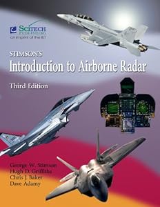
I'm glad to see a useful update to this classic from Scitech. They seem to take an active, positive role in technical publishing. I hope SciTech has updated the instructional infrastructure as well. I was working at Hughes when the original came out and bought a copy through the employee purchase. We joked that it was the "Classics Illustrated" version of radar textbooks. While airborne radar is a major part of the subject, there are many other areas of the technology which need to be covered.

I've been teaching a radar class using Skolnik's Introduction to Radar Systems 3rd edition, and it is obviously in need of an update. McGraw Hill had zero in the way of instructor support, and had even lost the problem solution set. They had no plans for an update. I'm considering switching texts to Richards "Principles of Modern Radar: Basic Principles", published by Scitech as well, as painful as that might be, for its improved technical coverage, matlab supplements, and enhanced instructional resources.

Monday, February 24, 2014

Curtis Wright Radar Scan Conversion Package | Radar Display


Radar Scan Conversion Package | Radar Display


The SoftScanRDS product uses SoftScan libraries to implement a turnkey radar display console application, able to render multiple radar sources in multiple windows under operator control. Radar video input from Curtiss-Wright Controls Defense Solutions’ acquisition hardware and from Curtiss-Wright’s RVP (Radar Video Processor) is supported. SoftScanRDS can be used to reduce the time required to implement a full radar console system. Available for Windows-based platforms, SoftScanRDS is also able to display track symbology from track reports supplied by RVP servers. -


Radar Scan Conversion Performance
This embedded computing radar product portfolio provides ultra-high radar scan-conversion  performance using unique graphics processor unit (GPU)-accelerated algorithms. Utilizing the power and performance of today's modern COTS graphics offerings, SoftScan provides unrivalled scan conversion performance with minimal CPU utilization.

Through SoftScan radar data can be displayed in a range of formats – Plan Position Indicator (PPI), A-Scan and B-Scan. SoftScan supports input of polar format radar video directly from radar acquisition hardware or from an RVP Server through a standard network connection. GPUs provide the signal processing power necessary for supporting powerful algorithms that prevent holes and spokes in the displayed image even in applications that require zooming in at long range, while
ensuring the display of all single point targets.

- See more at:
http://www.cwcdefense.com/products/video-graphics/radar-display-scan-conversion/softscan-radar-scan-conversion-package.html#sthash.9CKGywoG.dpuf

▶ ARPA Video Manual Acquisition

▶ ARPA Video Manual Acquisition - YouTube


Published on Jul 23, 2013
In 1960, the U.S. Maritime Administration developed a 10 target  automatic radar plotter with manual and guard ring automatic acquisition,  true and relative vectors, and with collision threat alarms and a trial  maneuver capability. In 1971, MARAD made this type of "computer aided"  plotter mandatory on all MARAD subsidized tankers. Sperry developed a 20  target, manual acquisition, predicted area of danger plotting equipment and  lotron developed DIGIPLOT, which plotted 40 target vectors with fully  automatic all area acquisition of the targets. IBM introduced their Maritime Integrated Bridge System that was automatic acquisition of 20 targets and included Transit Satellite Navigation and an Adaptive fuel saving autopilot for improved steering.

The International Maritime Consultative Organization (IMCO) deliberated  over two years on the United States proposal for mandatory carriage of  "MARAD equivalent" automatic radar plotters on all vessels above 10,000  grt. In November 1979, a minimum standard was agreed upon, as well as a  worldwide fitting schedule, starting in January 1984 and continuing over a  five year period, depending on vessel type and size. The original 1960  MARAD prototype could probably meet the IMCO standard with only minor  changes, mainly including the addition of 4 history dots with coice of 1 or 2 minute spacing. This concept showed up as an indicator of other surrounding vessels course and speed but was too slow to be considered as a useful maneuvering aid in traffic and the USCG adapted the Digiplot less than 15 second prompt course calculation to take forward to the IMO for the minimuum standard ARP on a radar PPI display.

The IMCO 10 target minimum operational ARPA standard set requirements for an aid  which will prevent collisions at sea and in relatively open ocean waters.  Although the systems are also intended to function approaching or leaving  harbors; the minimum IMCO standard does not require the radar plotting  equipment to work in high traffic density or in narrow waters or restricted  waterways when pilots would normally be aboard and added a second higher standard for 20 targets that could provide an indication of the direction of othr vessels in one minute and a fully very accurate course and speed to tight specified tolerances in four close passings.

The technology is now available today and is a much lower priced third generation  system whose ARPA calculated vectors are displayed on an e-chart, exceeding the IMCO minimum standards by a factor of 6 that now offers the potential for aiding a pilot in the safe navigation of the vessel in and out of harbors in dense traffic and in restricted waterways, are currently on the market. Now DIGIPLOT is the only example now resuming production.

Automatic radar plotting aid - Wikipedia, the free encyclopedia


Sunday, February 23, 2014

Patents related to RADAR PPI Display Technology

Patents related to RADAR PPI Display Technology
radar digital ppi range scale change - Google Search

Patent WO1981000022A1 - Ppi display for radar and synthetic symbology - Google Patents
Abstract
A complete frame of radar data is stored in real time in the memory (20) addressed by the converter (21) in accordance with antenna azimuth. PPI display (43) includes a rapid non-real radar time rotating scan by deflecting the beam along the azimuth sweeps thereof under control of X-rate and Y-rate signals provided for each sweep. Additionally, concatenated straight line strokes for synthetic symbology are displayed on the PPI display (43) under control of X-rate and Y-rate signals. The X-rate and Y-rate signals are applied sequentially to X and Y binary multipliers (49, 50) under control of the pattern memory (42) in order to generate clock signals at a frequency proportional to the rate signals. The clock signals are then applied to X and Y position counters (53, 54) respectively for generating the X and Y deflection signals via the digital-to analog converters (55, 57).


Patent EP2430472A1 - Combining data from multiple radar signals on a single plan position ... - Google Patents
Abstract  
In certain embodiments, a method for combining data from multiple radar signals on a single PPI includes receiving, from a first radar device having a first angular range of visibility, first radar signal data corresponding to the first angular range of visibility. The method further includes receiving, from a second radar device having a second angular range of visibility, second radar signal data corresponding to the second angular range of visibility. The method further includes performing compensation processing on at least a portion of the second radar signal data to form modified second radar signal data that is correlated to the first radar signal data. The method further includes combining at least a portion the first radar signal data with at least a portion of the modified second radar signal data to form combined radar signal data and generating, based on the combined radar signal data, a display on a radar PPI display.


Patent CA1057435A1 - Off-center radar display circuit - Google Patents
Abstract
In a radar PPI displays, digital techniques are utilized to allow an operator to move the point about which the radial trace beam rotates to a point remote from the center of the radar viewing screen and including movement off the screen without actually moving the display beam off the screen. A sweep signal generator detects the location of operator positioned off-center point from the setting of off-center control and is responsive to radar range scale and antenna position signals to generate appropriate ramp deflection sig-nals in the proper time sequence to accurately display a selected portion of the plan position indication upon the entire area of the viewing screen. A beam control circuit is responsive to the same signals as the signal generator and to a radar start pulse to determine the exact time the PPI display beam is to be turned on to display selected portions of the plan position indication. In this manner, the display beam is never deflected off the screen but is selectively blanked and unblanked and swept across the viewing screen to display the selected portion of the plan position indication upon the viewing screen as if the radar trace originated off the screen. The signal generator and control circuit cooperate such that when a target under study is in the middle of the screen when range scale is changed, the target will still be in the middle of the screen except that it will be expanded or contracted according to the range scale change.

Patent CA1136740A1 - Marine radar including anticollision unit - Google Patents

Abstract
Abstract A bright display radar system having anticollision capabilities in which received signals are digitized at a rate determined by a radar range setting and displayed at a constant relatively slow rate independent of the range setting. A computer based anticollision unit operates in response to the relatively slow digitized received signals so that targets may be tracked equally well at short and long ranges. Two sets of operator actuable switches are provided for controlling the anticollision unit. A first set of switches is provided which correspond directly to the most commonly used computer operating functions. The second includes an alphanumeric keyboard which may be used to actuate subroutines stored in a physically separate read-only memory which operates only in response to the alphanumeric keyboard.

Patent US3789403 - Digital line graphics control on range scalable radar crt display - Google Patents
Abstract
In a radar PPI display, the cathode-ray tube beam is intensified during a selected sweep in a predetermined pattern to generate an identifying pattern of line segments or dots on the sweep. The pattern is controlled by a range counter used to generate the sweep. Upon scaling the range, the clock pulse rate to the range counter is changed, thereby permitting the same stage, or stages, of the range counter to control intensification of the range sweep.

Patent WO2007035484A1 - Radar scan conversion for plan position indicator - Google Patents
Abstract
An angular scan interval may be divided into one or more sweep sectors for display. Polar (r, θ) coordinates may be calculated for rectangular (x, y) coordinates at each pixel of a display interval by computing polar (r, θ) coordinates in an interval of 0 to π/4 and by applying mapping equation sets. Bounds of a block of polar radar (R θ) coordinates that map to a given (x, y) coordinate may be computed. A mechanism to associate the bounds of the block in polar radar (R θ) coordinates and the rectangular (x, y) coordinates may be created. Bounds associated with the x-coordinate in a sweep sector may be calculated. A maximum of the x-coordinate bounds to xmax and a minimum to Xmin may be assigned accordingly. Bounds associated with the y-coordinate in the sweep sector may be calculated for each x-coordinate. A maximum of the bounds of the y-coordinate to ymax and a minimum to ymin may be assigned accordingly. Bounds of the block of polar radar (R θ) coordinates for each rectangular (x, y) coordinate computed from the mechanism may be retrieved. Radar observed parameter values scanned within the corresponding retrieved block bounds may be retrieved. Average or maximum parameter values within the block on the display may be displayed at the rectangular (x, y) coordinate.

Patent CA1199095A1 - Ppi to raster display scan converter - Google Patents
Abstract
PPI TO RASTER DISPLAY SCAN CONVERTER
Abstract A raster display apparatus for converting radar input data which is formatted to produce a Plan Position Indicator (PPI) presentation on a cursive display to a format which achieves a PPI type image on a raster display. The apparatus generates radar images on a raster display screen which appear as targets having continuous arcs of the proper length around the placement position of a radar. Average video levels within successive discrete fixed azimuthal standard angle increments are stored in a radial buffer memory for various increments of range. These video levels are used for all points within the presently active standard angular increment. Radial distance of a given image is computed for changes in orthogonal components such as X or Y using simple prestored sine and cosine functions. Conversion calculations comprise primarily additions using adders. The video amplitude of the image displayed is equal in amplitude to the video level of the input data stored in the radial video buffer memory for the standard angle being processed.
Processing of successive standard angle increments proceeds in approximate synchronism with the input data being provided in a cursive display format.

Patent US4224621 - PPI Display for radar and synthetic symbology - Google Patents
Abstract
A complete frame of radar data is stored in radar real time addressed in accordance with antenna azimuth. The PPI rotating display scan is generated by deflecting the beam along the azimuth sweeps thereof under control of X-rate and Y-rate signals provided for each sweep. The X-rate and Y-rate signals are applied sequentially to X and Y binary rate multipliers which generate clock signals at a frequency proportional to the rate signals. The clock signals are applied to X and Y position counters respectively for generating the X and Y deflection signals via digital-to-analog converters. Sequential application of the X and Y rate signals to the X and Y rate multipliers generates the rotating scan. The radar data stored in memory is accessed in accordance with the azimuth address in synchronism with the generation of the azimuth display sweeps. The stored data provides the video signal for the display tube so as to generate the radar display. The rotating scan is generated in non-real radar time at a rapid rate. X-rate and Y-rate signals are also applied to the binary rate multipliers for generating concatenated straight line strokes to display synthetic symbology. ΔX and ΔY signals are utilized to control the lengths of the strokes.

Patent US4224619 - Symbology writing apparatus for radar plan position indicator displays - Google Patents
Abstract
Symbology is written on a radar plan position indicator display with a rotating beam deflection field. The PPI radar range is quantized into range increments and digital data representative of the symbology to be written are inserted into a shift register which is clocked in synchronism with the range sweeps to provide interleaved digital data to the video input of the display. The normal radar video data is combined with the symbology data so that the symbology and normal radar returns are simultaneously written in real time. A portion of the symbology generating apparatus provides a manual acquisition marker comprising a range ring and an azimuth geometric figure. A range switch gates a clock pulse signal into a range up/down counter for incrementing and decrementing the number therein, the digital output of the counter being representative of the range of the range ring. The decoded digital output of the range counter is loaded into the shift register for bit serial application to the video input to the display. A manually operated azimuth switch similarly increments and decrements an azimuth counter, the digital output of which being compared to the radar antenna azimuth signal for positioning the azimuth geometric figure in azimuth. The symbology writing apparatus also includes a portion for providing alphanumeric or other localized symbology. These symbols are stored in a character table in the various orientations required for the plan position indicator display and written via the output shift register at azimuth and range coordinates provided by the system, the data therefor being interleaved with the data for the manual acquisition marker.
Patent US4206461 - Radar system with improved visual detection of long range targets - Google Patents
Abstract
A radar system in which the time duration of video pulses corresponding to echo returns is increased as a direct function of the range of the return. On a PPI visual indicator, the visibility of long range targets is thus enhanced by increased size without distorting the display of short range targets and clutter.

Patent US4663630 - PPI radar apparatus - Google Patents
Abstract
A PPI radar apparatus is constructed such that even when a transmission time cycle of radio waves is varied by switchover of a distance range to any of short, middle and long distance ranges, a sweep display time cycle of a radar video signal received in any of the distance ranges is maintained constant at all times; the sweep display time cycle is determined to meet the middle distance ranges, in the short distance ranges in which the reception time of radio waves is short, the video signals are written in storage means in real-time and then displayed by readout of the video signals at a low speed in synchronism with the sweep time cycle, in the long distance ranges in which the reception time of radio waves is long, the video signals are written in storage means in real-time and then displayed by a number of readouts in one sweep display time cycle; and the video signals written in a plurality of storage means are parallelly read out and a mean value or peak of the read-out video signals is obtained by arithmetic operation to thereby enhance the signal-to-noise ratio of the radar image.

Patent US4845501 - Radar video scan converter - Google Patents
Abstract
A marine radar system having a multi-plane video memory for storing scan-to-scan integrated video data used to raster scan the CRT. A scan converter generates cartesian or x,y addresses for the video memory and synchronous with the generation of each, x,y address, generates a range address for reading corresponding video data from an r,θ or polar memory. The x,y addresses are generated along azimuth sweeps by incrementing one coordinate by a pixel unit and the other coordinate by a trigonometric function. The unit coordinate and the trigonometric function are determined by the 45 located. The pixel unit incremented coordinate is offset by one pixel unit from the origin of the azimuth sweep in alternate octants to address pixels along the octant boundaries and thereby avoid display artifacts.

Patent US4005415 - Automated radar data processing system - Google Patents
Abstract
An automated radar data processing system comprised of signal processing cuitry and programmed general purpose digital computer apparatus performs detection, classification and tracking of all targets within the field of view of the radar. The signal processing circuitry includes an adaptive video processor which receives the raw radar video signals and which derives a threshold from the noise, clutter, or electronic countermeasures signals in the immediate vicinity of the target and passes only those incoming signals which satisfy the detection criteria in terms of signal to noise ratio and extent. The signal processing circuitry is interactive with target track data derived and stored in the computer apparatus, so that the specific signal processing applied to any target by the adaptive video processor is optimized in accordance with the track status of that target. The proposed system also better enables a human operator to take a system management position wherein he can set up or establish data processing conditions so as, for example, to optimize target detection in highly variable or critical environments.

Patent US4754279 - Scan converter for radar - Google Patents
Abstract
In a scan converter for converting polar-coordinate radar data into a standard video display scanned at a 100 ns per pixel rate, the reading of sixteen x-y pixels into the video buffer, writing of two polar pixels into the x-y memory, and fading of four x-y pixels in the x-y memory can all be accomplished in a single 1600 ns time slot by using a nibble mode of addressing with an x-y memory made up of four standard 64K chips operable in parallel. In another aspect of the invention, radar data can be written into the x-y memory of a scan converter at double that rate without affecting the read or fade capabilities by configuring the x-y memory chips in such a manner that a given address on the memory chips represents a group of adjacent pixels of one line of the display and a corresponding group of pixels of the next adjacent line of the display.

Patent US4862154 - Image display processor for graphics workstation - Google Patents
Abstract
The present invention provides for the combining of image and graphics data in a high-performance raster graphics workstation. It allows the definition of windows on the screen, the dynamic control of the position of those windows, the magnification factor (integer zoom), and a color translation table, corresponding to each window. All these functions are under user control. Response time of 10 new frame buffers generated per second provides a "real" time response.
Patent US4873515 - Computer graphics pixel processing system - Google Patents
Abstract
A line-filtering antialiasing apparatus for a computer graphics display, with a set of parallel pixel processors functioning independently in a line drawing system and with plotting apparatus assigning individual pixels to the processors so as to track to the line. An optimum number of sixteen processors filter proximity data based on the vertical distance from a pixel center to the line center for shading pixels to gray-scale intensity in an area of influence four pixels wide. Line terminations are extended and shaded at the termination area. Pixel values for individual lines are summed to develop a total display image.

Patent US5315305 - Scan converter for a radar display - Google Patents
Abstract
Radar data vectors of a desired number of pixels in length are scan converted, at a desired angular rate. A complete 360 degree radar data scan is maintained in memory. A raster image of a desired number of pixels in size and of arbitrary position and angular orientation with respect to the radar scan in memory is outputted. The resolution of the raster output image is varied to adjust its update rate. A high resolution, motion stabilizing radar display is provided and a multiresolution capability is available to eliminate image artifacts attributed to raster image update rate.

Patent US5414429 - Device for converting output data of a radar for the display thereof on a ... - Google Patents
Abstract
A device for converting data for display on at least one television screen associated with a videographic memory, the output signals of the radar comprising at least one videographic signal and scanning data, the device comprises a processor for processing the different radar output data, an analog/digital converter for digitizing the videographic signal, a videographic signal converter for compressing the digitized videographic signal, a distance marker generator for generating distance markers, a polar to Cartesian converter for converting the standard of the coordinates of the data contained in the signal from a polar coordinate system into a Cartesian coordinate system, an intermediate memory for receiving and storing the compressed videographic signal and the distance markers, an output buffer memory for receiving and storing the output signals of the intermediate memory and the polar to Cartesian converter and an interface for controlling the memory as a function of the data contained in the buffer memory. The device includes an after glow processor connected to the interface, for controlling the contents of zones of videographic memory to produce an after glow phenomenon of certain points of the radar image.

Saturday, February 22, 2014

GA-ASI $95M Contracts for new Gray Eagle Ground Control Stations

Defense.gov Contracts for Friday, February 21, 2014

Universal Ground Control Station (UGCS)
General Atomics-Aeronautical Systems, Inc., Poway, Calif., was awarded an $18,109,374 modification (P00014) to contract W58RGZ-12-C-0057 for changes to the Universal Ground Control Station.  Fiscal 2013 other procurement funds in the amount of $8,873,593 were obligated at the time of the award.  Work will be performed in Poway, Calif., with an estimated completion date of Nov. 30, 2015.   Army Contracting Command, Redstone Arsenal, Ala. is the contracting activity.
 
The Mobile Ground Control Station (MGCS)
from General Atomics is a UAS control center,
enclosed in a either a 24-foot shelter or 30-foot trailer,
used to control one GA-ASI aircraft
General Atomics-Aeronautical Systems, Inc., Poway, Calif., was awarded a $76,215,685 modification (P00015) to contract W58RGZ-12-C-0057 to change the Gray Eagle Portable Ground Control Station to a mobile ground control station.  Fiscal 2014 other procurement funds in the amount of $35,842,972 and fiscal 2013 other procurement funds in the amount of $2,453,283 were obligated at the time of the award. Estimated completion date is Nov. 30, 2016.Work will be performed in Poway, Calif. Army Contracting Command, Redstone Arsenal, Ala. is the contracting activity.


General Atomics gets Army go-ahead for UAV universal ground control station integration - Military & Aerospace Electronics


REDSTONE ARSENAL, Ala., 11 May 2011. Plans by the U.S. military to consolidate its numbers of ground control stations for unmanned aerial vehicles (UAVs) may be moving forward with the announcement Tuesday of a contract to General Atomics Aeronautical Systems Inc. in Poway, Calif., to integrate a Universal Ground Control Station.

The U.S. Army Contracting Command at Redstone Arsenal, Ala., awarded General Atomics Aeronautical Systems a $9 million contract Friday to work together with AAI Corp. in Hunt Valley, Md., which is the developer of the Army's Universal Ground Control Station, or UGCS. The contract
calls for General Atomics to procure hardware, help AAI with development funding, and complete integration of the UGCS with the General Atomics  MQ-1C Grey Eagle UAV, which is an extended-range version of the General Atomics Predator UAV.


Building a Better Ground Station

The Army is pursuing the Universal Ground Control Station (UGCS) to improve upon its decade-old One System Ground Control Station (OSGCS). UGCS is designed to operate three types of Army unmanned aircraft: Gray Eagle,  Hunter and Shadow. While UGCS retains the exterior of OSGCS—an HMMWV-mounted shelter for both Hunter and Shadow and a 5-ton truck for the longer-endurance Gray Eagle—the new consoles and software that operate all three aircraft are identical.
“You can take soldiers and instead of training them on multiple ground control stations, you can train them on one ground control station,” said Lieutenant Colonel James Kennedy, the Common Systems Integration (CSI) product manager in the Army’s Unmanned Aircraft Systems Project Office. “Then, regardless of where they are stationed, they’ll be able to fly whatever aircraft their particular unit is using.”

It’s Better to Share: Breaking Down UAV GCS Barriers 


UAVs have played a crucial role in gathering intelligence in the US military’s wars in Iraq and Afghanistan. There are thousands of UAVs gathering and distributing valuable data on the enemy, but each system uses its own proprietary subsystem to control the air vehicle as well as receive and process the data. Yet commanders need access to information gathered by all types of UAVs that are flying missions in their area of operation. Recognizing this shortcoming, the Pentagon began an effort in 2008 to break down the proprietary barriers between UAV systems and create a single GCS that will fly all types of drones.
 

Friday, February 21, 2014

MUOS satellite demonstrates polar communications capability


Mobile User Objective System
MUOS is the next generation narrowband military satellite communication system that supports a worldwide, multi-Service population of users in the ultra-high frequency band. The system provides increased communications capabilities to newer, smaller terminals while still supporting interoperability with legacy terminals. MUOS is designed to support users that require greater mobility, higher data rates and improved operational availability.

Lockheed Martin MUOS satellite tests show extensive reach in polar communications capability | 2014-02-04 | Microwave Journal

Lockheed Martin recently demonstrated that the U.S. Navy’s Mobile User Objective System (MUOS) satellites may help solve communication challenges in the arctic. Now people spread over thousands of square miles could have access to more secure, reliable communications. During company-funded tests, MUOS voice and data signals reached much farther north than previously thought, just 30 miles and 0.5 degrees of latitude shy of the North Pole.

A team demonstrated Wideband Code Division Multiple Access (WCDMA) capability using three different radios as far north as 89.5 degrees, under peak orbit conditions. This inherent voice and data access is well beyond the 65-degree system requirement.


Published on Jan 31, 2014
Activity in the arctic is growing as the polar sheet cap recedes. More people, shipping, exploration and search and rescue expose the need for secure communications to protect the region. However, getting satellite communications signal is extremely difficult. But not anymore. Watch how Lockheed Martin's engineers and partners confirmed untapped capability through the U.S. Navy's MUOS constellation.

F-35's Computer Software Problems - R2-D2 or HAL? | "I'm sorry Dave"?

About: Life Cycle: Software Development | F-35 Lightning II
As of January 2014, more than 88 percent of the required F-35 software is currently flying. Approximately 97 percent of the required software has been coded and less than 250,000 lines of code remain to be written.

In 2013, the F-35 program flight tested the first four iterations of Block 2B, the software configuration the Marines will use to declare Initial Operating Capability. Pilots conducted sensor fusion operations, executed night landings on the USS Wasp and dropped both air-to-air and air-to-ground ordnance. The software is proving to be stable and performing well.

Report: Software Issues May Delay F-35 for US Marine Corps | Defense News | defensenews.com
Is the F-35's Computer R2-D2 or HAL? | Defense Tech

Marine Lt. Gen. Robert Schmidle said, “We need to have the ability to override the algorithms that are built into that system to determine whether an aircraft is safe to fly or not,” he said during the interview. “I didn’t design ALIS. I didn’t develop ALIS. I’m trying to do everything I can to make ALIS work for us.”

The rigidity of the system invited comparisons not to the friendly robot R2 of Star Wars, but to the more menacing machine HAL 9000 of the science-fiction flick, “2001: A Space Odyssey.”

In addition, the plane’s reliance on software and information technology makes it a target for hackers, Schmidle said. “It’s kind of like you using your smart phone to do banking,” he told Martin. “You are taking a greater risk than if you walk down to the teller at the bank and say, ‘Hey, this is what I wanted to do.”

While Schmidle said he’s “confident” that the military will be able to protect the aircraft’s data networks, he also acknowledged that “it’s not going to be easy and it’s not going to happen overnight.”

The hardware is also showing cracks, and may need redesign

SNAFU!: F-35 jet stress tests may be halted for as long as a year?!

Reaper strikes again

Report: US Drone May Have Killed Dozen Civilians | Military.com

WASHINGTON - A U.S. military drone strike in Yemen last December may have killed up to a dozen civilians on their way to a wedding and injured others, including the bride, a human rights group says. U.S. officials say only members of al-Qaida were killed, but they have refused to make public the details of two U.S. investigations into the incident.

Kelli Serio - From Petty Officer to Pin-Up | Under the Radar

Spirit of War Military Blog: Know your Resources by Kelli Serio

From Petty Officer to Pin-Up | Under the Radar
From Petty Officer To Pin-Up | Pin-Ups For Vets
Never saw anything like that on my PPI.

Incredible drone video shows Ukraine's riot battlefield from above

Incredible drone video shows Ukraine's riot battlefield from above


A drone films protesters clashing with police forces as tires and Molotov cocktails burn in Kiev's Independence Square. The battle has started again, after yesterday's failed truce. At least 75 have been killed on since last Tuesday, according to Ukraine's government officials.

Iridium GO! or Aurora: Which is the Better Choice for Satellite WiFi?

Iridium GO! or Aurora: Which is the Better Choice for Satellite WiFi?

Which is the Right Unit For You?

Aurora
  • Dimensions: 7.28 in Diameter (185mm), 7.09 in high (180mm)
  • Weight: 4 lbs
  • Temperature: -22° F to 158° F (-30° C to +70° C)
  • Certifications: FCC, CE, and RoHS
  • WiFi: 802.11 b/g
  • Power: Power over Ethernet
  • Easy installation
  • Fixed installation
  • Good for larger installations (like a big boat or a building) where the ease of running Ethernet cable is a plus
  • Good for seasonal users who don’t want to be locked in a year-long contract
  • Available in Mid-March. 
  • Easy for grab and go, ditch bag
  • Small, mobile, Ruggedized
  • Military-grade ruggedness (MIL-STD 810F)
  • Ingress Protection (IP65)
  • Potential for unlimited data plans
  • Good for year-long users who don’t mind a year-long contract
  • Potentially good for really high data users (if, indeed, Iridium releases an unlimited airtime plan)
  • Available (maybe) in Late May. 
  • Dimensions: 4.5"x 3.25" x 1.25"Stable, lay-flat design 
  • Flip up antenna 
  • Built-in menu/status display
  • Wi-Fi device ready
  • App API for developers
  • Robust accessory platform

Thursday, February 20, 2014

Maersk MV Cragside being fitted for MSC as a Special Operations ‘Mothership’

Milcom Monitoring Post: The Navy’s Getting a Big, Secretive Special Operations ‘Mothership’
MSC is adding a bunch of new hardware to Cragside to allow the vessel to function as a floating base for up to 200 troops and their weapons plus small boats, helicopters and the aforementioned jet skis, which the Navy and Air Force have begun buying and which Navy SEALs could use to sneak along enemy coastlines.


Cragside should be able to sail 8,000 miles at a time at speeds up to 20 knots and in 20-foot seas, needing resupply only every 45 days. The shipyard is adding a highly-secure communications room, a gym and weapons lockers. After all, you can’t house all those Army Delta Force troopers and SEALs without ample weapons lockers and gyms.


The sleek, capacious ship—already fitted with a rear ramp for loading vehicles—is also getting a flight deck big enough for the largest, heaviest U.S. military helicopter, the Navy’s MH-53ECragside will also be able to support Army Apache gunships, Navy patrol helicopters, Special Operations Command Little Bird attack copters and even Marine and Air Force V-22 tiltrotors.


Cragside’s hangar must be big enough to hold two Navy helicopters at the same time for maintenance—and has to have the special, subtle lighting that allows crews to use night-vision goggles.
The Navy’s Getting a Big, Secretive Special Operations ‘Mothership’  — War is Boring — Medium

I wonder if they'll turn off the AIS transponder.


M/V Cragside
CRAGSIDE - IMO 9457218 - ShipSpotting.com - Ship Photos and Ship Tracker
Last known position:
51°54’28.08” N, 4°21’44.35” E
Status:Moored
Speed, course (heading):
0kts, 155° (155°)
Destination:
Location:Rotterdam;immingham
Arrival:21st Dec 2013
07:00:42 UTC
Last update:
1 month 29 days ago
Source:AIS (AirNav ShipTrax)
M/V Cragside 

Military Sealift Command to charter Maersk ship for ‘maritime support’ | Longshore & Shipping News
Military Sealift Command (MSC) has awarded a contract to Maersk Line Ltd. in Norfolk, Va., to charter a ship to function as a “maritime support vessel.” The $73 million contract, with options for four 12-month options for a potential total value of $143 million, calls for a U.S.-flag, twin-shaft vessel for use into November 2014, and potentially through October 2018. The ship is MV Cragside, said Jim Marconi, a spokesman for MSC, though he added, “We can’t provide details relating to the ship’s mission.Cragside has an overall length of 633 feet, a beam of 85.3 feet and a displacement of 20,650 long tons.


Maersk Success Stories

Special Mission Ships

U.S. Navy and the U.S. Air Force
Special Mission Ships
MLL provides personnel, operational and technical support for seven special mission vessels deployed to the Far East region of operations. These vessels have been supporting mission sponsors since 1984 and are valuable assets to the U.S. Department of Defense. Our highly-skilled mariners execute navigation, deck, engineering, galley and auxiliary services. The span of the services include managing maintenance and overhaul subcontracts, repair parts, equipment, services, regulatory inspections, husbanding agents and port costs, fuel, training, utility services and transportation. Many special mission vessels have been de-activated, stored and then re-activated under MLL’s supervision and management.


Raytheon IDS Portsmouth gets up to $200M for AN/SQS-20A for LCS Minehunting

Defense.gov Contracts for Wednesday, February 19, 2014


LCS 1/2
Raytheon Integrated Defense Systems, Portsmouth, R.I., is being awarded a $35,545,309 fixed-price-incentive contract for the purchase of three  AN/AQS-20A sonar, mine detecting sets with ancillary equipment.  The AN/AQS-20A sonar, mine detecting set is a mine hunting and  identification system with acoustic and identification sensors housed in an underwater towed body. The acoustic sensors are designed for the  detection, classification and localization of bottom, close-tethered,  and volume targets in a single pass.  The identification sensor is  designed for the identification of bottom mines.  

The system will be  deployed from the Littoral Combat Ship as part of the Mine  Countermeasures Mission Package.


Remote Multi-Mission Vehicle (RMMV)
The AN/AQS-20A Sonar, Mine Detection Set, is a mine hunting and identification system with acoustic and optic sensors housed in an  underwater towed body with a fixed wing and controllable tail surfaces. The sensors are designed to detect, classify and localize bottom, close-tethered, and volume targets. The AN/AQS-20A will be deployed from Littoral Combat Ships (LCS) as part of the Mine Countermeasures (MCM) Mission Package (MP)
The AN/WLD-1(V)2 Remote Minehunting System (RMS) Remote Multi-Mission Vehicle (RMMV) tows the AN/AQS-20A.

The
AN/AQS-20A has four modes of operation: 
  • Single Pass Shallow (SPS) Mode - Bottom and moored mine coverage in a single pass 
  • Single Pass Deep (SPD) Mode - Moored mine coverage in deep water 
  • Volume Mine (VOL) Mode - Volume mine coverage at four times the area search rate 
  • Identification (ID SPS) Mode - Bottom and moored mine coverage in a single pass plus optical imaging of bottom mines.


The combination of sonars enables the AN/AQS-20A to detect and classify mine-like objects from the seafloor to the near surface in a single pass. The system also has an identification capability that
delivers high-definition images of bottom mines providing the operator with both range and contrast data that combines to form a three-dimensional image during post-mission analysis to aid in mine
identification.

The AN/AQS-20A modes enable the system to give timely and accurate information on the location and position of mines so they can be quickly neutralized by minesweepers and by the Airborne
Mine Neutralization System (AMNS).


More than half the work will be done in Portsmouth RI

This contract includes options which, if exercised, would bring the cumulative value of this contract to $199,692,601. Work will be performed in 

  • Portsmouth, R.I. (56 percent); 
  • Tucson, Ariz. (21 percent); 
  • Pawcatuck, Conn. (6 percent); 
  • Middletown, R.I. (5 percent); 
  • Glen Rock, N.J. (2 percent); 
  • Windber, Pa. (2 percent); 
  • Cincinnati, Ohio (1 percent); 
  • Big Lake, Minn. (1 percent); 
  • Woodland Hills, Calif. (1 percent); 
  • Lewisburg, Tenn. (1 percent); 
  • Huntsville, Ala. (1 percent); 
  • Poway, Calif. (1 percent); 
  • North Springfield, Vt. (1 percent), and 
  • Hampton, Va. (1 percent), 
and is expected to be completed by February 2015.  Fiscal 2013 and 2014 other procurement, Navy contract funds in the amount of $35,545,309 will be obligated and will not expire at the end of the current fiscal year.  This contract was competitively procured via the Federal Business Opportunities website, with two offers received.  The Naval Sea Systems Command, Washington, D.C., is the contracting activity (N00024-14-C-6302).

Tuesday, February 18, 2014

'Flying Leathernecks' To Unveil Northrup Grumman EA-6B Prowler @ MCAS Miramar

EA-6B Prowler

Community Invited To Attend Special Event Being Held February 28th

The Flying Leatherneck Aviation Museum and Historical Foundation welcomed the Northrop Grumman EA-6B Prowler to Marine Corps Air Station Miramar today. The aircraft is being prepared for display, and the museum is inviting the public to attend the unveiling ceremony this month.
The event will be held February 28th at 1400 PST at the museum on MCAS Mirimar.

The Northrop Grumman (formerly Grumman) EA-6B Prowler is a twin-engine, mid-wing electronic warfare aircraft derived from the A-6 Intruder airframe. The EA-6A was the initial electronic warfare version of the A-6 used by the United States Marine Corps in the 1960s. Development on the more advanced EA-6B began in in 1966. An EA-6B aircrew consists of one pilot and three Electronic Countermeasures Officers, though it is not uncommon for only two ECMOs to be used on missions. It is capable of carrying and firing anti-radiation missiles (ARM), such as the AGM-88 HARM missile.

Prowler has been in service with the U.S. Armed Forces from 1971 through the present. It has carried out numerous missions for jamming enemy radar systems, and in gathering radio intelligence on those and other enemy air defense systems. From the 1998 retirement of the United States Air Force EF-111 Raven electronic warfare aircraft, the EA-6B was the only dedicated electronic warfare plane available for missions by the United States Navy, the United States Marine Corps, and the United States Air Force until the fielding of the Navy's EA-18G Growler in 2009.

The Foundation actively supports the operation of the Marine Corps Air Station (MCAS) Miramar Command Museum (Flying Leatherneck Aviation Museum) located on MCAS Miramar. We accomplish the mission by providing a volunteer base to support day-to-day operations and by providing financial support to augment austere DoD budgets.
(Image provided by Flying Leathernecks Museum)
FMI: www.flyingleathernecks.org